


oh no sorry if u misunderstood me....meant to say 40's could be included to give a approximate figure on torque n horse power. Sidedrafts i can tolerate for daily use but not the mupiness really.

oh no sorry if u misunderstood me....meant to say 40's could be included to give a approximate figure on torque n horse power. Sidedrafts i can tolerate for daily use but not the mupiness really.
1973 mk1 escort
1982 Toyota corolla ke70
1988 mk4 escort
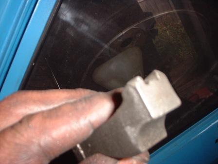
i've now got the cam a kent FR30 high torque, otherwise known as a caravan cam
kent quote cam lift as 0.290 a quick check showed we werent short changed as it meassured up at 0.300
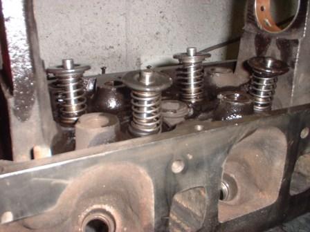
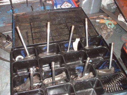
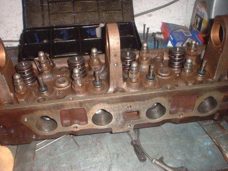
i've fitted the valves and reatainers with some light springs, normally people use x/flow rocker shaft springs, i havnt got any of them but some bmw rockershaft springs cut in half work just as well.
the beauty here is the valves can easily be removed and refitted without using a spring compressor and the rockers can simply be slipped in annd out without any trouble or touching the adjusters
theory says if the valve geometry is right, after adjusting valve cleaances full lift should come out as kent specify, the geometry should be pretty much spot on on the exhaust side because the valves are new std ones and the valve seats only just needed a very light cut
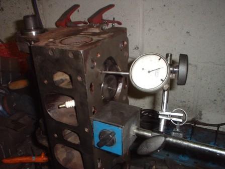
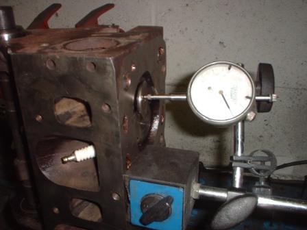
kent quoted full lift on the exhausts as being 0.469 and no1 measured up at exactly .0469- result, no 2 ex
the inlet lifts werent so goodthey all came in at between 0.435-0.448, well short of the specified 0.482, despit my leaving the valves as high in the combustion chamber as possible, but its only to be expected, the bigger group one valves have longer than std stems, this looses lift and were missing enough to effect power, this is the NUMBER ONE reason why many pintos do not make the power they should.
roughly speaking for every 0.010 valve lift missing the valve need shortening by 0.030.
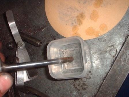
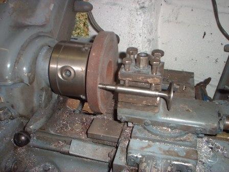
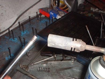
some valve facing (herniea machines) can shorten valves, mine cant
but a grind stone in the chuck of my lathe and an old valve guide to hold the valve do a perfectly good job
most of the inlet valves needed just over 0.100 off them (2.5mm) one of kents slightly odd sized/shaped followers caught me out a touch though, as i shorten the valves but by not quite enough, meassure up again then shorten them a bit more, one of them gave me a fraction too much valve lift 0.04 on the first cut, a light lick of either the valve or valve seat would put that right but im sure 0.004 extra lift wont make any difference.
one other slight suprise was the followers all hit the inlet retainers, as the exhaust ones didnt but all the lift figs came good it must be because the inlet valves have there grooves a bit higher up the valves, not a big proplem just a touch of grinding required on the followers to remove the corners
Last edited by Graham; 23-08-2008 at 22:09.
That's stuff I didn't know.
Very educational.
great to see the 'mechanics' of putting an engine together, would never have the opportunity to see it otherwise, and i dont think i'll ever get round to doing it myself.. no space, no facilities and defiantly not enough knowledge

http://www.gofastnews.com/board/tech...-dynamics.html
Whole article, is worth a read.So what produced this Avenger’s steam engine like low speed torque and race winning top end? It was not small intake valves as some suggested. It was not a reconfiguration of the engines big bore short stroke to a small bore, long stroke. Nor was it countless other erroneous old wives tales for moves that are supposed to produce a torquey engine. For the record straight long strokes do not make more low speed torque than short strokes. I can disprove the ‘it must make more torque because of the long arm’ fallacy both mathematically and from dyno tests. Also the valve size thing cropped up so many times I was ready to about tear my hair out. I was even fed this size the valves for the power band fallacy at a Superflow Conference. I am going to be really categoric about this that to make best low speed torque the engine needs the valves to be as big as can be crammed into the space available.
Well so much for what it ‘was not’ that made the wide torque band a reality. The real world factors were about as follows. First a head with really good flow and as much swirl as I could find, although, it was still only about average in that quarter. Second, valves that used almost the entire cylinder diameter and since this was a short stroke engine the bore was big for a 1500 cc unit and that meant the valves were too. Ports the appropriate size (very important). Great attention was given to the twin two barrel side draft Dellorto 40 DHLA carbs auxiliary Venturi’s to ensure a uniformly fine fuel atomization. An independent runner induction (one barrel per cylinder) and a well specced exhaust system in terms of lengths, diameters etc. All this produced, even at very low rpm, a highly combustible mixture in the quenchless chamber shape this engine had. The final frosting on the cake came from a diligent calibration of the mechanical and vacuum advance delivered by the distributor.
If I had to isolate one factor that contributed to this engine’s wide ranging performance it would be it’s obviously superior to the norm, in cylinder mixture dynamics.
after all the follower swapping and valve length adjusting its vital to keep all the valves retainers and follower with the correct cylinders, this wurth box is ideal.
the group1 inlet valves i used are left over new old stock from years ago so i wasnt too sure what material they were made of i just knew they were once piece valves, a quick check with a magnet showed the stems to be magnetic so they are not stainless, which is good news, as that means they can be case hardened, not a hard job, just heat the end until its a nice red colour and quench in cold water, i did them all then went round them all again, i dont know how hard they are but a quick check with a file shows they are now certainly a lot harder
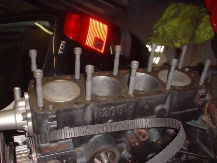
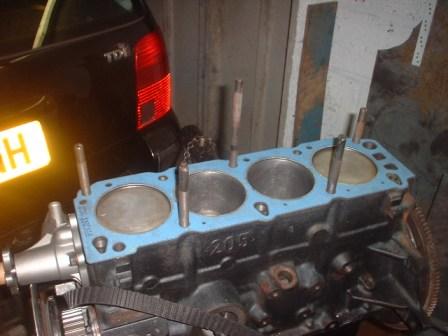
going back to the block whenever a lot of metal has been skimmed off you must check that the head bolts wont bottom out in the block before the head is torqued down, otherwise the bolts can bottom out you can think they are tight but the head isnt actually clamped down properly.
i had previously used this block with a head skimmed 0.100" so with only 0.054" missing (0.014 head skim, 0.020 block skim 0.020 thinner gasket) i should be ok, but you never know especially with a different set of bolts.
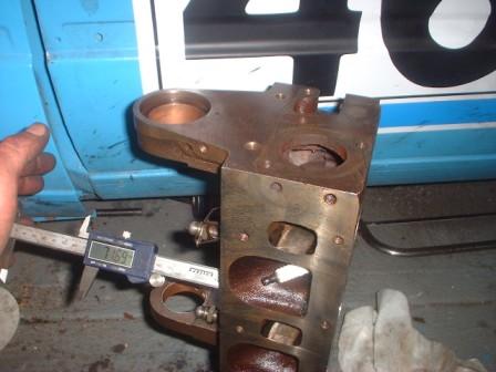
1st off run a tap preferably a plug tap ( these have a quite square end) down the bolt holes to clean out any rust/muck etc,
screw in the bolts as far as they will go finger tight
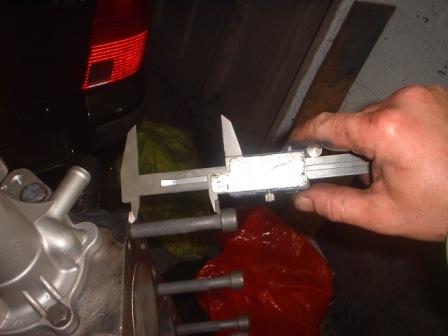
finding the one that sticks out the most
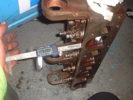
meassure the space between top of block and underside of the bolt head
then meassure the depth of the bolt holes in the head
the head came up 4mm taller than the longest bolt, which will actually become 5mm with a head gasket in place, which will be enough to allow for the torquing of the bolts later. had i had insufficent its quite ok to shorten the bolts, some makes/types of engines which only have a short threaded section need washers under the bolt heads or if thats not feasable then the threads in the block need tapping out deeper
Last edited by Graham; 02-09-2008 at 08:50.
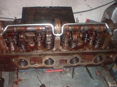
reassembling the head is now a simple follow the haynes manual jobbie, just dont mix the bits up!
making sure to smoother the cam in cam lube
nothing too special about refitting the head either, except that i like to use several old head bolts with the tops cut off them and a screwdriver slit cut in the ends of them so the head gasket has something to locate it when the heads put on,
the head gasket is a felpro bolts were new std torx, i would of preferred to use spline bolts but didnt have any
Hello
A problem I have noticed with the long pad followers you are using is that they don't have enough clearance between the two "ears" that locate the rocker on the end of the valve.
Basically the rocker catches the end of the valve if there isn't a large enough taper on the end of the valve like all the std valves have.
The best solution is to use a thin grinding disc in a dremel and modify the rockers to give the valves a little clearance.
I have had to do this with a few engines, noticed it on the first motor when I was setting the rocker clearance, the rocker wanted to jam and pull the valve.
Poor design as usual.
Will you be going to a rolling road after the motor is built? Would be interesting to see what bhp and torque you get out of the motor.
I use the same head bolt trick for gasket location, new (old type) splined bolts can be bought from burton power
Jason.
Last edited by RWD fords rule; 11-09-2008 at 13:08.
the engines likely to end up on a rolling road at some point, thats rather out my hands though, dunno when it wil lbe either the car its going in is under resto at the moment.
how much torque is likely to be produced?? 140 lb ft?? or thats going overboard?
1973 mk1 escort
1982 Toyota corolla ke70
1988 mk4 escort
i'd like to think somwwhere between 140 and 150 BUT whether it will ever achive that would depend on how well the std ford EFI can be tricked and tweeked into fueling the engine correctly
Hi, not trying to pick holes in anything you are doing as you are certainly much more knowledgeable in this subject than me, however when you did the valves you hardened them but didnt case harden them, case hardening means that the metal needs to be carburised, case hardened then core refined so that you have a compact metal grain structure on the outside where the valve would get worn and a large grain structure in the centre which would make the valve much less brittle than if you just harden it by quenching which would give a compact grain stucture throughout the whole valve,
I agree scooby.
I don't like to be the bearer of bad news but quenching the end of the valves in water will cause the end of the valve to be very brittle and there is a chance the valve will break clean off at the bottom collet groove and drop!
I hate getting this sort of bad news, cos you know it makes sense, sorry Graham.
So how should you harden them?
by making them drink irn bru and wear a tea shirt all winter.Originally Posted by Dave
You don't!
If you use steel valves that haven't got stelite tips they are already hard enough so you can shorten them safely, they are hard but not brittle.
Stainless valves cannot be shortened because they are too soft. All stainless valves have a stelite tip.
An example of how brittle steel gets when quenched in water:
Try welding two bits of mild steel together, then quench them in water, this will make it very brittle and the weld will easily break, let it cool in air and the weld will bend before it breaks.
Ha ha, you could try that either lol
What will torque curvebe like?
1973 mk1 escort
1982 Toyota corolla ke70
1988 mk4 escort
all i'll say on that one is that i'm carefull not to get the whole valve end hot those are the very same valves and process we used to use in all the big valve pintos that were done were i used to work back in 1980-1990 something we did 100's of heads and never had such a failure, which included some very high reving engines, whilst this is quite a low revving road engine,
i've been involved with building and repairing engines for over 20 years i stand by my work on this engine if i thought it would end in disaster i wouldnt of done it,
without going into the inns and outs of the fiances of the deal i can say this engine was built at a cost lower than mates rates, so i havnt made anything from it infact if you factor time in at ANY sort of labour rate no mater how cheap i have made a thumping great big loss on it ,
however i will add for you all to see, which includes the engines owner who is on ts and reads this thread
IF it does suffer a failure due to my build techniques it will repair ANY damage FOC
Last edited by Graham; 17-09-2008 at 08:17.
If you have gotten away with it for so long then maybe it will be ok, I wouldn't try it though.
Why are you not charging more for the engine then?
I would feel used if I built anything for a loss!
Time + experiance = no money
Jason
i shall not be shortening/hardening valves on the linford pinto which will spend its life at rpm way beyond what this one will go
life isnt always about money, i do charge for what i do normally, occasionally i will make an exception for a friend or someone i feel is deserving, also in this case it also made for an interesting thread to add somthing back into the ts site which most of us get a lot out of for so little cost.
it also depends a bit on what im actually doing and if its something i want to do out of interest etc, some years ago for a friend i worked out how to build a close ratio gearbox for a fwd escort using nothing but std off the shelf ford parts, i made nothing from it, but i learned a lot and have since built another couple of similar boxes on the knowledge learnt and made some money from it in the endclose ratio escort/fiesta box anyone??????
I know what you mean, helping out friends, or someone you know will make full use of and appretiate the mods you are doing for their car.
With friends I do give a lot of free time, but I still expect to make some sort of a profit, I wouldn't expect someone to work on something for me and then not pay for thier hard work thats all.
Im sure graham will be repaid in liquid form
Keep on it mate its almost there now
talking generaly (no experiance of valves) you can buy a case hardening powder / compound. the work piece is heated then dipped/quenched in the compound. this can be repeated. the result is a surface richer in carbon and hence case hardened. usefull for pins and wear parts etc.
willing to share that bit of info? at the moment using a BC gearbox on my 1.8swift engine which is back in my swift sedan.
agree 100% that life isnt always about money..
1973 mk1 escort
1982 Toyota corolla ke70
1988 mk4 escort
How much would you be prepared to pay for such info

i think thats a clue
just joking
ookkkk...it wouldn't be so hard to figure out it i could find out the number teeth/gear ratio of each box.... have made similar gearboxes for suzuki but generally the boxes dont take the abuse...so i'm tryin my luck wid the BC box but info seems to hard to come by on the net.
Last edited by SidewaysMk1; 18-09-2008 at 17:59.
1973 mk1 escort
1982 Toyota corolla ke70
1988 mk4 escort
if you must keep cluttering up my pinto thread.....................
most 1600 BC boxes have the following ratios
1st 3.16
2nd 1.19
3rd 1.28
4th 0.95
5th 0.75
most of the smaller engined boxes and the diesels have
1st 3.58
2nd 2.05
3rd 1.35
4th 0.95
5th 0.76
most bc boxes have a 6 bolt crownwheels in the following ratios
1.1cc 4.06
1.3cc 3.54
1.4cc 3.84
1.6cc 3.84
1.6xr3i 4.27
the 4.27 final drive is also found in S1 rst
S2 rst has a 8bolt crown wheel with a 3.82 ratio which is also used in diesels
if you can find one a XR2i gearbox has a 4.1 ratio final drive
most fiestas had 3.8 final drives or 4.06 if they have 1.1 or 0.9 engines
the best ratios for the BC box actually come from a IB5 gearbox from 1700 puma as they are considerably closer having a lower 3rd, 4th and 5th gears, BUT to use that box you would have to use a hydralic clutch or do what i do which as to fit them inside a BC casing, but they dont fit straight in, the main and lay shafts are slightly different lengths the lay shaft has a modified bearing which needs un modifying and you need to either space the bc casing out a bit or use a bit of casing from a Ford KA, the puma final drive is quite long but if you can also find a gearbox from a 1.25 zetec fiesta you can fits its 4.27 final drive, the IB5 boxes mostly use 8 bolt crownwheels you you can fit S2 rst LSD's to them.
sorry, wasnt trying to be a smart arse when i pointed that out and your valves shouldent break as you say i was just pointing it out incase someone else thought that was case hardening and went and did it themselves, overdid it and bust their engine...hows the engine coming on btw?all i'll say on that one is that i'm carefull not to get the whole valve end hot those are the very same valves and process we used to use in all the big valve pintos that were done were i used to work back in 1980-1990 something we did 100's of heads and never had such a failure, which included some very high reving engines, whilst this is quite a low revving road engine,
actaually the engines finished and gone, im just dragging my feet on the thread, i didnt take many more pics so theres not a lot left to post until its in and working
OK so say we substitued the Efi wid a 1 downdraft or sidedraft weber. could the same torque figure be obtained?
1973 mk1 escort
1982 Toyota corolla ke70
1988 mk4 escort
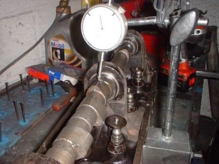
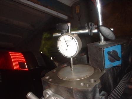
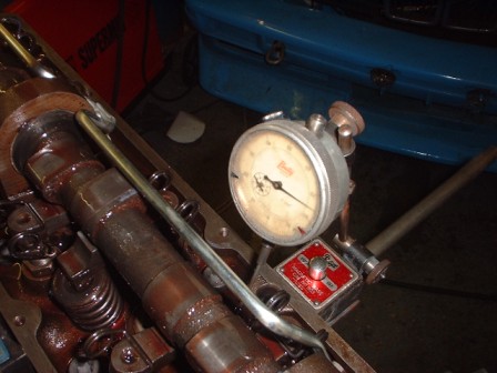
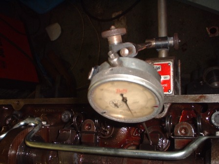
short engine built up, time to get an accurate TDC,
i attach a timing disc to the crank and squash a big blob of plastoscene into the front of the engine and getting the engine to tdc with a dti gauge i insert a thin rod into the plastoscene to act as a pointer, pointing it at tdc, i then rock the crank and note the number of degrees on the degree wheel a couple of thou either side of TDC, true TDC is exactly half way between each figure, the pointer is usually a bit out so i just move it a tad and recheck
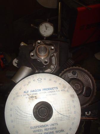
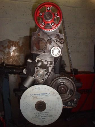
having lined the cam up using a std cam pulley, i bolted the head on and torqued it down, swapped the std cam pulley for the vernier and tensioned the cambelt with the vernier pulley "loose" then tightened the vernier
timing the cam was simply a matter of turning the engine untill full lift on no 1 inlet valve was reached, noting the actual lift figure, winding the the engine back a bit until, then forward but stopping when the DTI gauage showed the engine was a couple of thou away from fulllift, and i marked the degree wheel, continuing to turn the engine forwards go past TDC until the valve is at the same full lift fig as before, again mark the degree wheel, full lift will be exactly half way between your marks on the degree wheel, i cant remember how much but the cam was out by quite a few degrees, correcting it was simply a matter of loosening the vernier bolts and rotating the crank by the number of degrees it was out from the correct full lift figure, locking the vernier up and double checking the timing,
one thing i didnt like simply because it looked wrong is that the vernier ended up almost at the end of its adjustment ( i now seem to recall someone else complaining that kents alloy vernier doesnt have enough adjustment these nothing wrong with being at the end of the adjustment, its just unusla and doesnt look right, actually did the cam timing again, but this time moved the belt back a tooth on the vernier the results were same the vernier ended up near the end of its adjustment just at the other end this time.
cam cover on and the engine went off to its new home, so there wont be any updates until its fitted, but dont hold ya breath its going in a resto project.
the rebuild including a doner base unit came in somewhere between £750 £800 which included all new valves, complete cam kit, heavy duty cam bearings, rings, bolts etc etc but we were lucky with the base short block didnt need new pistons oil pump or a crank grind, in most cases you can add £250 straight away and if you have to pay someone do all the work including porting and assembly and checking then the engine would cost between £1500-£2000, at which point a secondhand zetec starts and a bag of retroford bits starts to look good value, but which ever way you look at it really is a budget engine rebuild
Last edited by Graham; 24-09-2008 at 01:14.
That is one cheap motor.
I usually time in a pinto by setting the bottom end to the full lift point, 108 atdc for example.
Then turn the cam to exactly full lift no1 inlet with vernier loose, torque down the head, fit belt and tighten, tighten one vernier bolt fully, bring back to tdc and round to full lift again, check for true full lift point and adjust timing if necessary, I usually get within about 4 degrees with that method.
Very similar to your method just that when you set the bottom end to the full lift degree there is no chance of valves hitting the pistons when you fit the head because the pistons are all well down the bores.
Yeah the kent alloy veriers are crap, not nearly enough adjustment, i prefer steel verniers because of this and also when setting the timing you can mark the pulley for true 0 timing, +4 and -4 degrees with a dremel.
Most important thing to do is turn the engine over by hand two full revolutions with the spark plugs removed, at each timing point, 0, +4, -4, so that you know valves aren't hitting pistons.
I'm sure that isn't a problem with your mild cam though.
Last edited by RWD fords rule; 05-10-2008 at 14:30.
generally i time teh cam before even fitting the head, i usually use DTI's to get both valves at equill fit at TDC, and then fit the head with the bottom end at true tdc, fit and tension the belt vernier loose then tighten veriner, marking the pulley has showed after the timing was swung on a RR it ends up where i set it,
i didnt use that method in this case simply because its an unusal engine spec with its big/std valve combo and very mild cam
I tried your method on the last two pinto's I tuned, marked the pulley for equal lift at tdc and also the advanced 3:2 inlet:exhaust ratio, it has worked noticeably well, haven't got the chance to test it out on a rolling road yet but it is interesting that you got max bhp at equal lift on tdc.
Would you use the same method for a 16v engine, setting them for equal lift at tdc while keeping the total overlap degrees the same?
Has this worked on many different types of engine ?
the equail lift tdc method also works best on bmw m10 engines which are also 8valvers, but then again thats what 99.9% of the time the cam grinders are actually trying to achive when they grind cams and should work best UNLESS there is something wrong with the ratio between the inlet and exhaust valve sizes or something else really wrong with the engine spec,
as for 16v engines i dunno as the only ones i have build have been std or near std with the exception of my 16v turbo bmw engine on that i initially built it timing both cams in to give the same tdc lift of 0.080, after a bottom end problem first time out i was very short on time reassembling it and just refitted std sprokets and teh engine had std factory cam timing whatever that is but its going to be very close to equil lift and a power run showed exactly the same result
I read all the post's on this topic and throughly enjoyed it. The expected power levels have been discussed several times in regards to the standard factory EFI. If a modified 32/36 or modified 38dgas ( modified as one of the other stickies describes) was fitted to the same spec engine what would the exptected power levels be at the rear wheels?
 Posting Permissions
 Reply With Quote
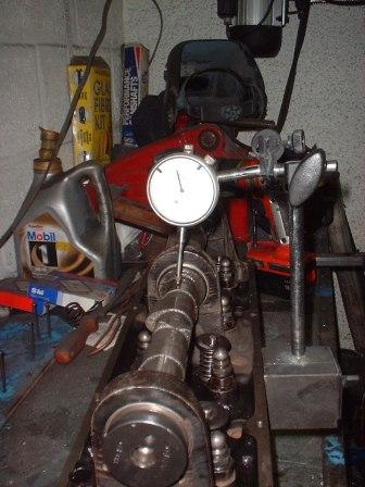


")


Bookmarks