


very nice, is there much in the way of mk2,s down there? i spotted 2 when i was in perth a few weeks ago

very nice, is there much in the way of mk2,s down there? i spotted 2 when i was in perth a few weeks ago
You don't see many on the road but there are quite a few hidden away in people's sheds that get used on the weekends mainly for competition.Originally Posted by cammy
I appreciate everybody's comments and I am keen to get on and finish it but I have some other things to sort out so it won't be done straight away.
Back to the build....
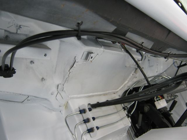
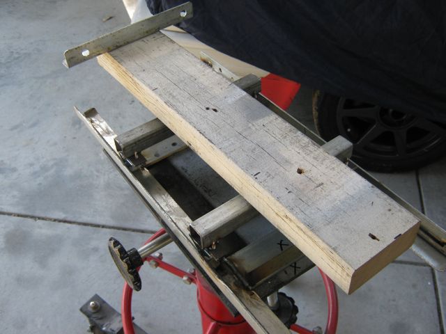
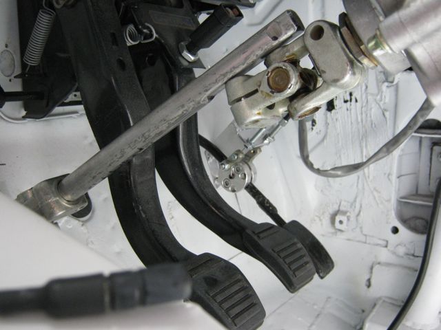
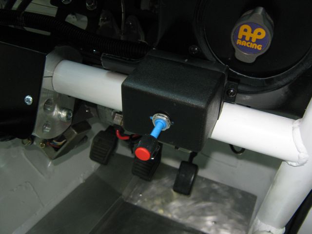
Originally I was going to route the throttle cables around the front of the engine and then through the firewall in the usual way but then I saw a under bonnet photo of a Den Motorsport Escort that showed the cables going through the firewall behind the engine which got me thinking that this is a better way to do it.
So now the cables run under the dash over to the RHS.
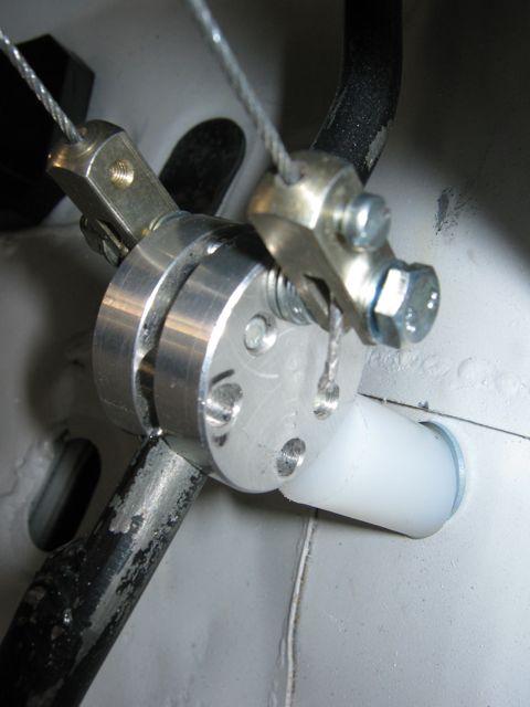
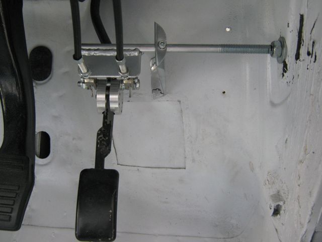
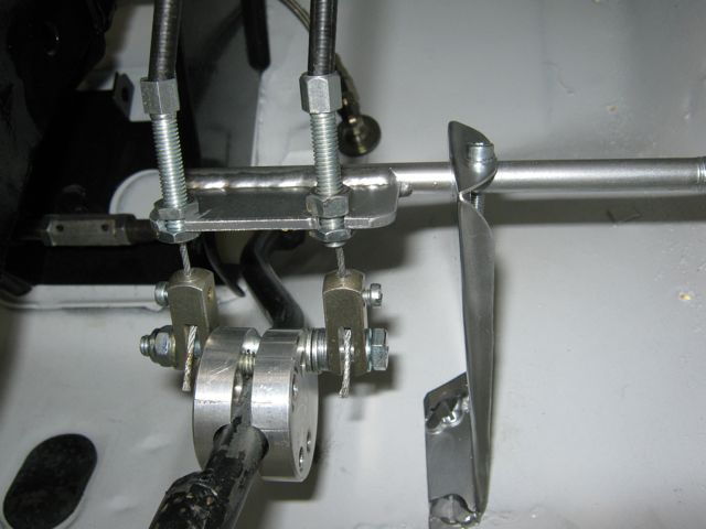
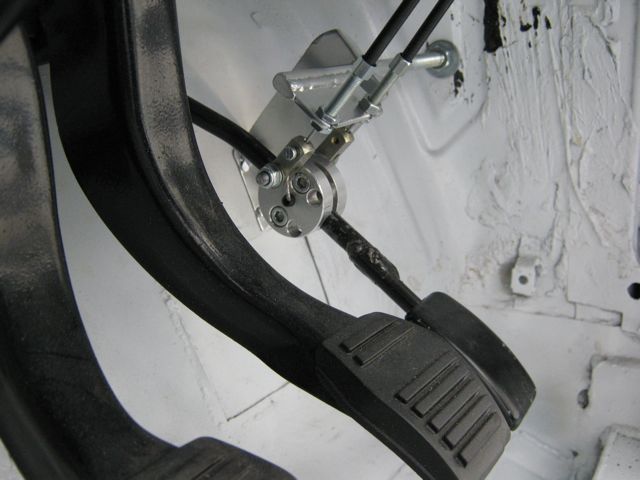
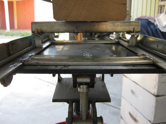
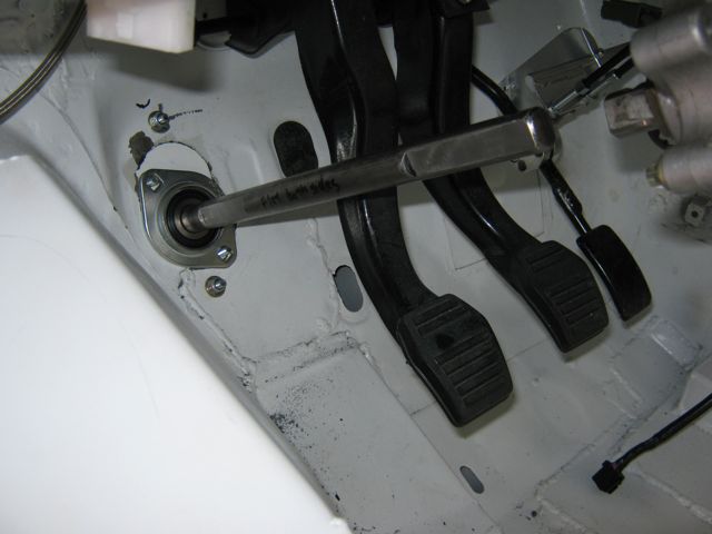
I spent a long time thinking how to connect the cables to the pedal so that they would be pulled and after some complicated ideas this simple way suddenly occurred to me.
The final touch is a stop on the firewall to eliminate strain on the cables at full throttle.
Very nice work mate, a good simple solution
http://escort.accelerator.org
1968 MK1 Escort 1300GT
1969 'Big Wing' MK1 Escort
1972 MK3 Cortina 1600XL
1984 Sierra XR4i
And other junk I don't like to talk about!
Thanks, I spent ages trying to work out how to get the throttle pedal to pull the cables when they were behind the pedal. I was thinking of things with rods and bell cranks and having to weld on the pedal , all very complicated and then I had a eureka moment that solved the problem. The KISS principle is always best
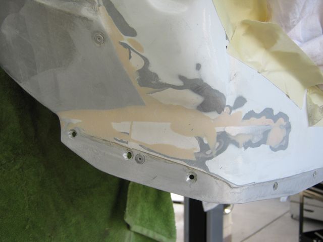
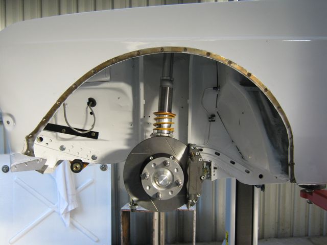
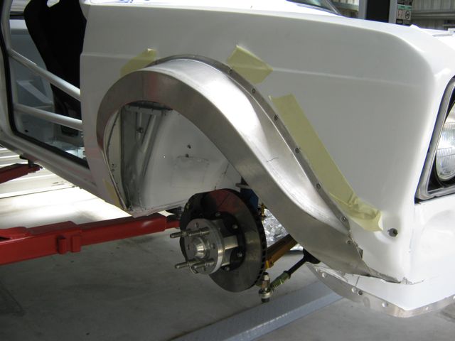
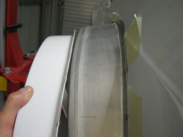
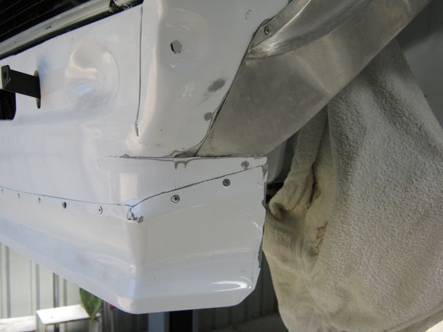
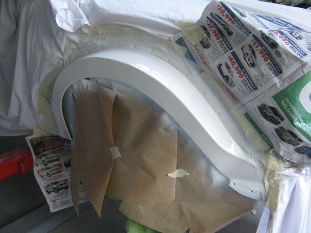
For the next job I took a big breathe and removed the front arches( luckily I had bolted them on so it was easy but it did mess up where filler blended the arch and spoiler).
I taped the new arch on and mounted the wheel ( I have replaced the front wheels studs with ones that allow a 10mm spacer to be used to get a bit more clearance for the calipers).
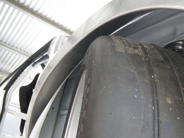
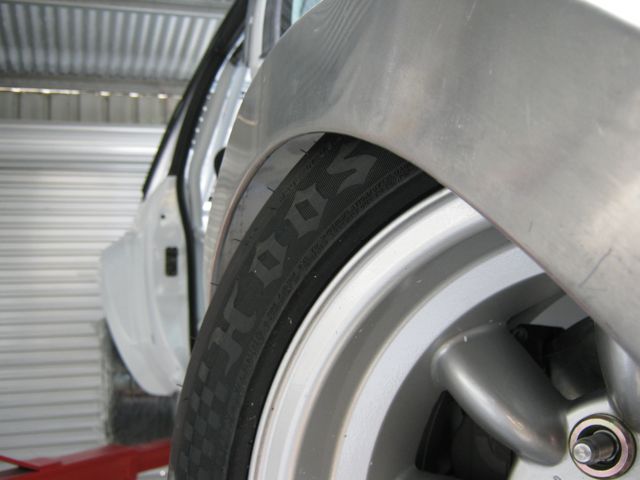
This allowed me to find exactly where the arch needed to sit to allow clearance between the tyre and the arch on full lock when the suspension is fully compressed.
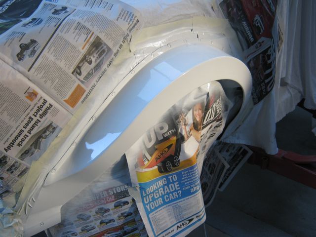
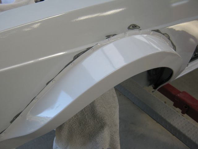
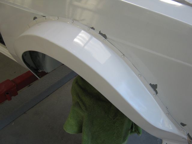
Luckily that point allowed the arch to sit right on the swage line. Photo shows the extra width of the new arches.
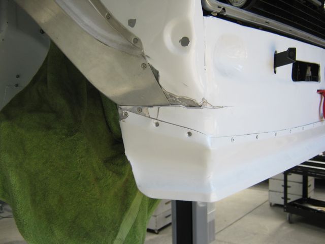
The front section needs to be blended in with filler.
Like this
You definitely are not afraid to redo previous work! I like that. I am sure you have said previously but what brand wheels are those again?
1970 Mk1 Escort Tarmac Rally Car
Unfortunately I haven't got an instruction manual for this project so I modify things along the way. The wheels are Performance Superlites. My tyre supplier insisted I use these but they don't do Group 4 ones. He was able ( with difficulty ) to get them to make a one off set for me. He has left the tyre business so there won't be any more.
I have been out of action for the last few days with a nasty cold. It is over 30º here so I don't know how that happened.
Got out to the shed today and painted the new arches.
Well done Bevan,lovely project
Thanks Torsten, your parts have helped
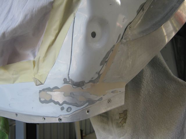
When I removed the arches I was hoping to get away with not having to paint the wing but the masking tape has removed some of the paint. I am not happy with the paint ,it seems to chip very easily even though a hardener was added. I will have to blend in new paint but will wait a few weeks for the paint on the arches to harden.
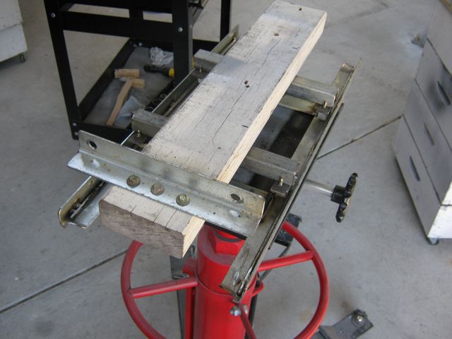
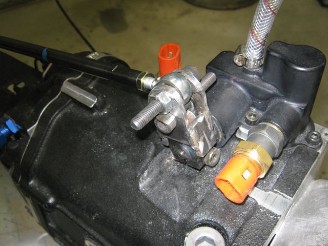
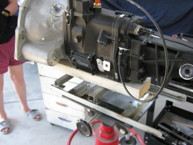
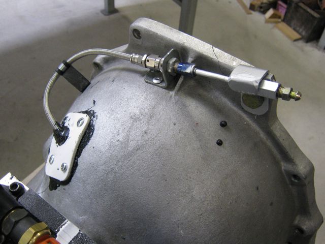
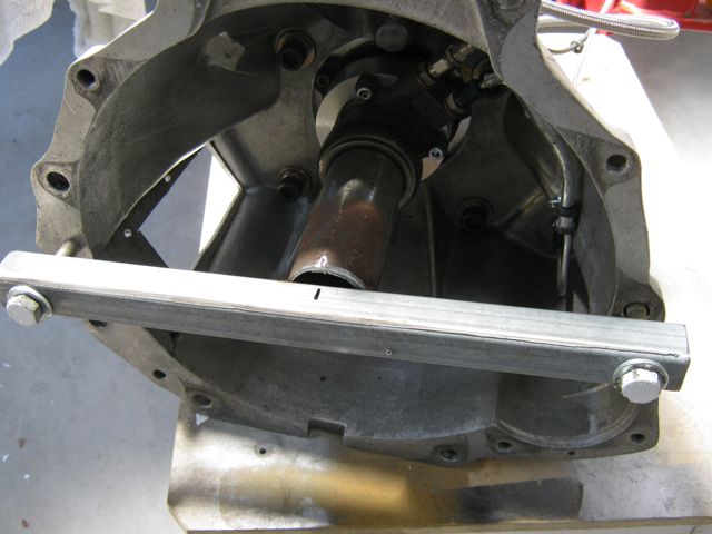
I have removed the gearbox to find out where the clutch plumbing is leaking. I made up a trolley system to mount on the gearbox jack to make removing/installing the gearbox easier.It worked a treat
Nice bit of work on your gearbox jack to make life easier , but think health and safety may want a word about your steel toe caped slippers
They are my girlfriend's "Japanese Safety Boots"
That's pretty bad about the paint mate - shouldn't come off that easily!
It is mainly near the edge where I cut the wing but it does chip easily. The only upside is it didn't cost much but in hindsight I should have sprayed it myself.
It has been around 40º here, luckily I have put an airconditioner in the shed so I have been cracking on.
Bleed plumbing for the clutch... take 2.
This time I hooked it up with the gearbox out of the car to check it is working correctly with no leaks.
While the gearbox was out I thought I would get the gear position display working. It was a good thing I did because I could not get it to work properly.
The problem was that the display figure would not match the selected gear no matter what I did. After a lot ofI realised that the problem was that the potentiometer was not turning in the correct direction. The barrel indicator moved anti clockwise going up through the gears but turning the pot anti clockwise the numbers decreased e.g. when the 1st was selected and '1' was displayed changing to 2nd the displayed showed 'R' and continuing changing up the display counted down
After a couple of hours trying to get it to work I gave up.
The next day it occurred to me that maybe the pot was wired incorrectly.After I bit of stuffing around to enable the +5v and ground to be interchanged it worked perfectlyThe loom had been wired wrong .... surely it was tested
Finally Santa brought me this so I can record my exploits ... when I get it going...
Nice bit of progress there mate
Did you find where the fluid leak was coming from then?
http://escort.accelerator.org
1968 MK1 Escort 1300GT
1969 'Big Wing' MK1 Escort
1972 MK3 Cortina 1600XL
1984 Sierra XR4i
And other junk I don't like to talk about!
I didn't find where the leak was but it must have been in the bleed line as that is all that I replaced.
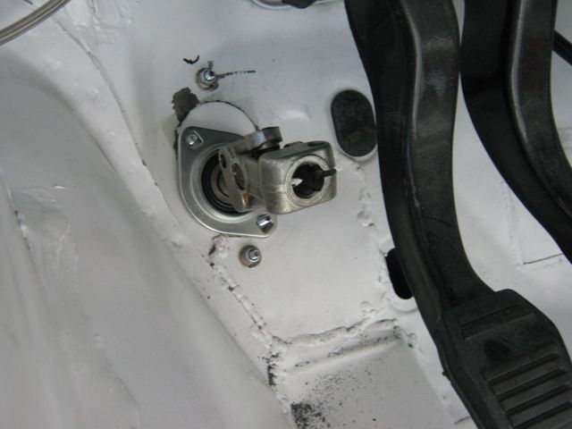
BTW I relocated the bleed screw because I didn't take into account that the bleed screw could only be accessed from underneath which meant that when the car was on the hoist it was very difficult to operate the pedal and top up the resorvoirIn the new place both can be done easliy
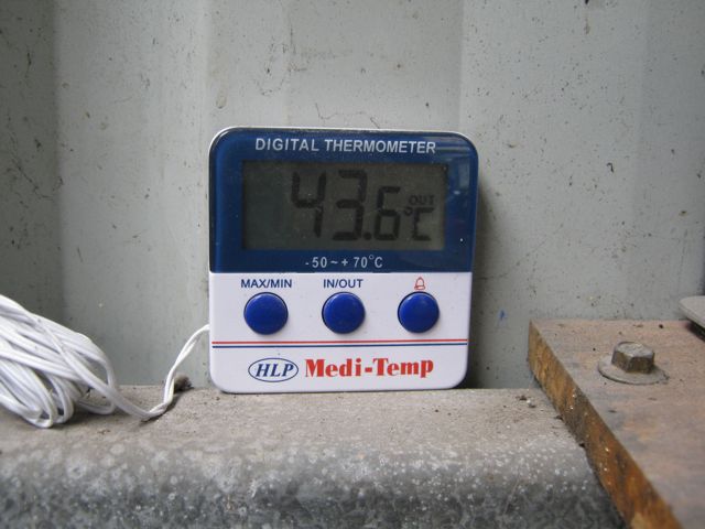
Today is the 7th day in a row that the temperature has been around 40º
This was how hot it was in the shed where the car is
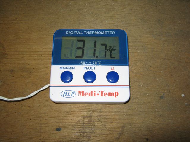
a bit cooler in my airconditioned workshop
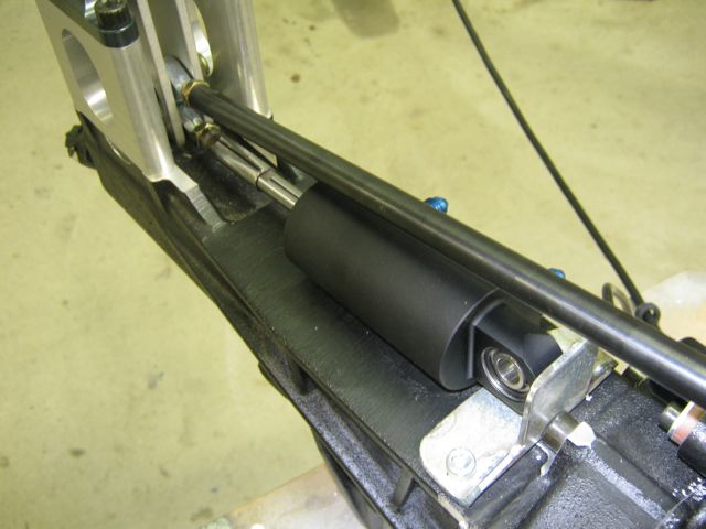
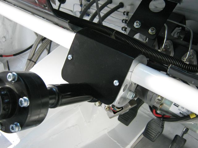
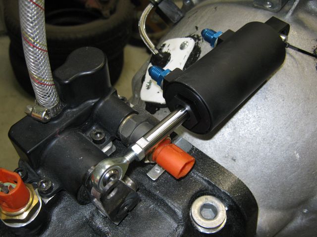
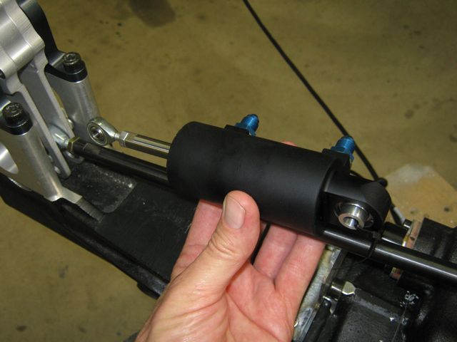
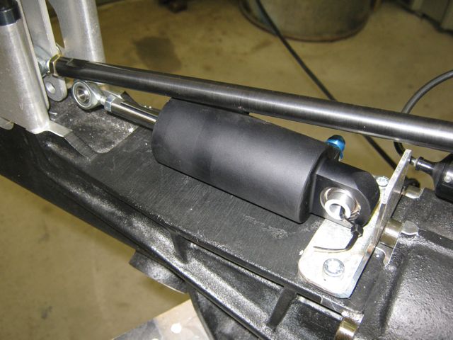
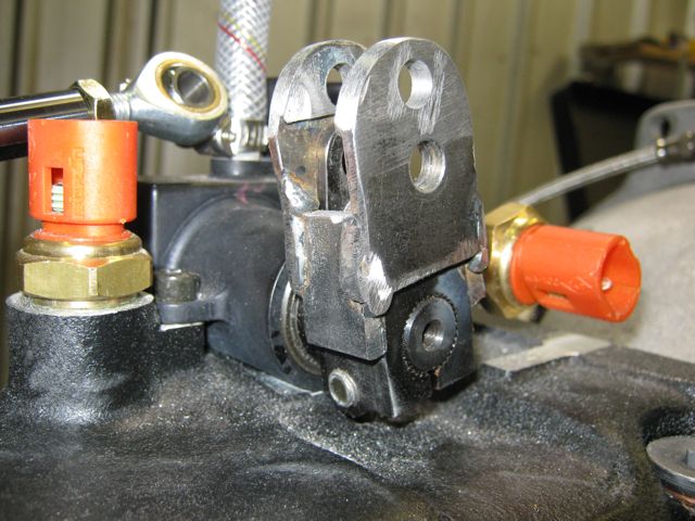
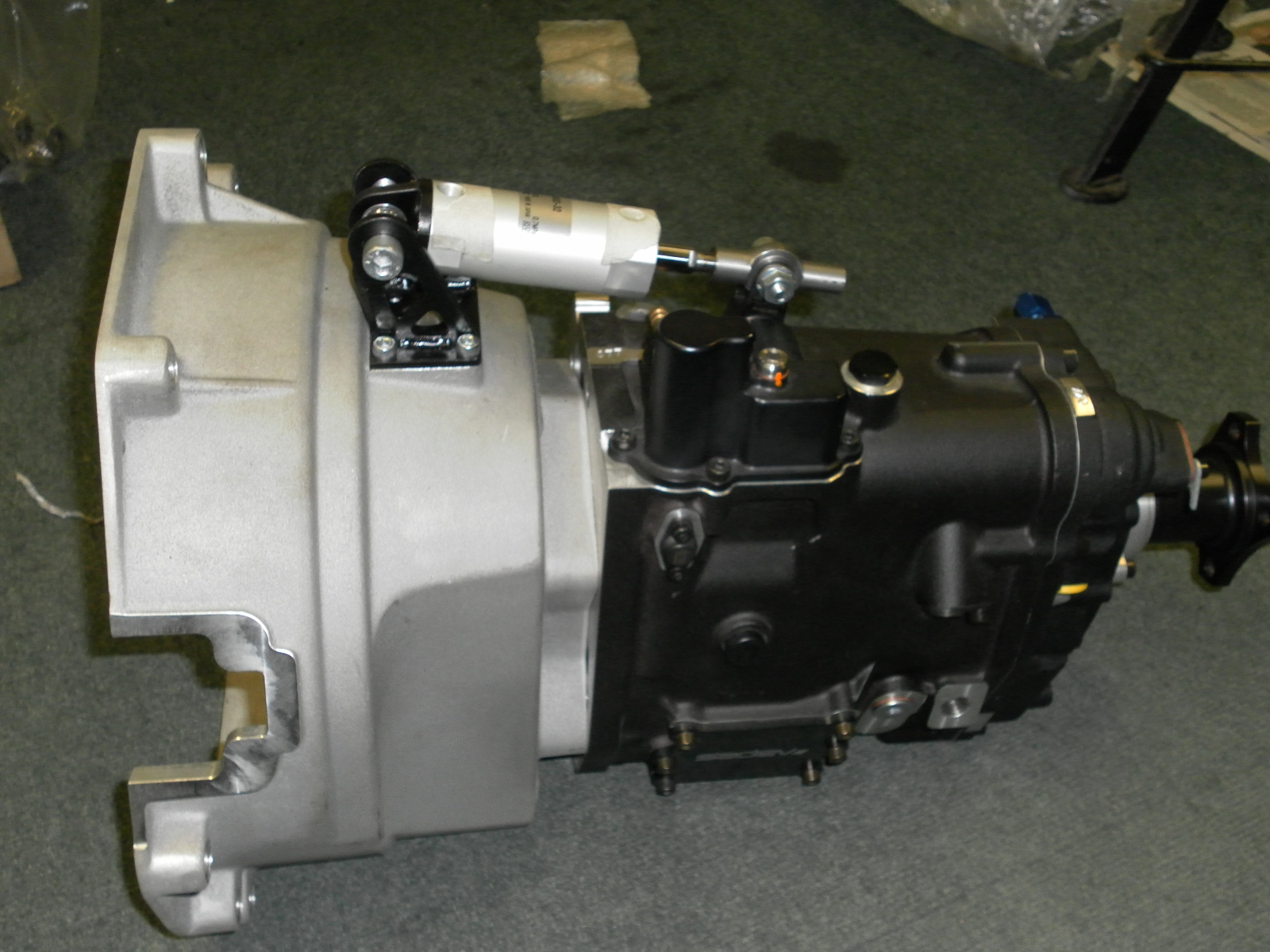
As it is too hot to work on the car I started on fitting the gearshift actuator for the paddleshift.
As usual I spent a long time working out where too mount it. Ideally it would act directly onto the shift peg
but there is not enough room.
Then I considered mounting it above the shift rod with it acting on the rod
Finally I thought of mounting it under the rod with it acting on the gearlever
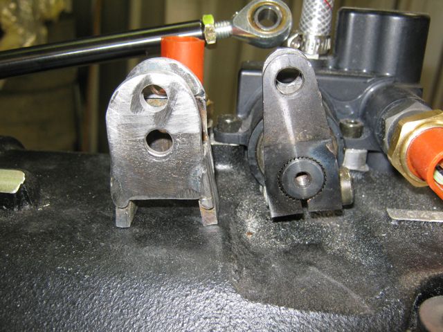
Before I could mount it I had to modify the shift peg. The actuator throw has to be 24mm or a bit less and with the standard peg the throw is 12mm so the pivot point on the peg had to be raised.
I made this extension to go on the shift peg so that the point on the gearlever where the actuator connects moves 24mm when the gears are shifted.
This is how I did it Bevan (just in case it's of any help)
I also have a shift peg that's longer than standard, off another model of Sadev gearbox, same spline and everything...
Check the travel on the shift peg is the same in each gear as well as up & down, mine seems to have slightly further travel in one direction, not that it makes much difference.
(double ended rosjoint works with back-up gearstick, ignore that)
Tom,that Duratec bellhousing makes mounting the actuator much easier in that position than with my Pinto bellhousing. I could have mounted it there but I would have needed to cut the tunnel again and I don't want to do more cutting.
Small amount of progress today.
The actuator needed an extension to reach the gear lever. I have used one of the rod ends from the shift rod temporarily. I will have to wait until everyone is back from their Christmas break next week to get another one.
Much cooler here now... only 28º in the shed
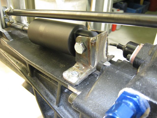
Completed the mount for the actuator
I will have to wait until I get another rose joint to test it.
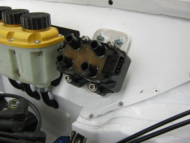
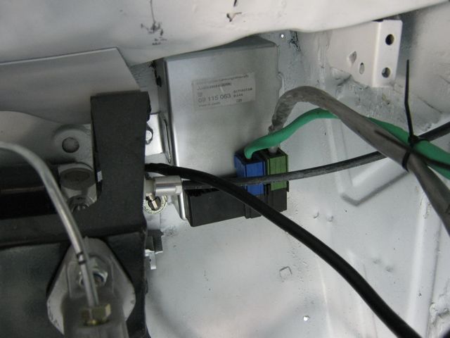
The coil pack is mounted on the back of the dry sump pump which is very neat but difficult to access so I have relocated it to the bulkhead.
First I had to make a plate to bolt to the bulkhead so that the coil pack could easily be removed
I was hoping to get away with just the 2 bolts on the top as it is difficult to get my hand down to attach a nut but it flexed to much so I had to add another bolt. By loading the nut onto a spanner and fixing it with masking tape I was just able to get the nut on.
Stunning!!
great work.
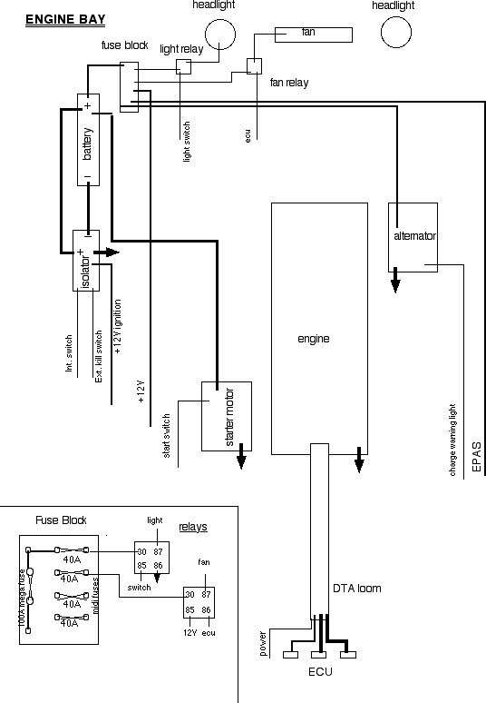
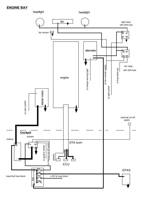
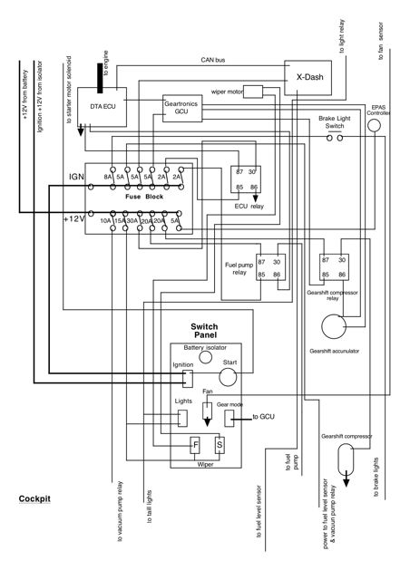
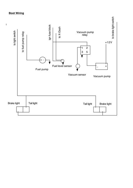
My head is still spinning after spending 2 days designing the electrical circuits.
These diagrams are the result but I am certain they will have to be revised... there is sure to be a mistake or two somewhere.
Now I have to make up a component list so I can wire it all up.
Well I new there would be a mistake somewhere. Lying in bed last nightI suddenly realised that I had not included the power feed to the wiper switch.
I also decided to change the power feed to the ECU from the ignition circuit to the 12V circuit to reduce the draw on the ignition circuit.
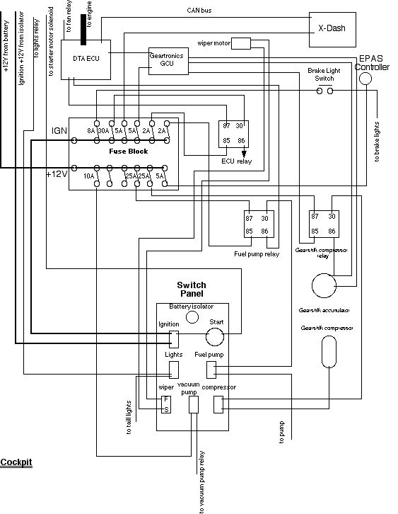
Revised diagram
I did a component list this morning and ordered most of it online.
Made this shelf to mount the ECU, GCU, fuse block and relay holder
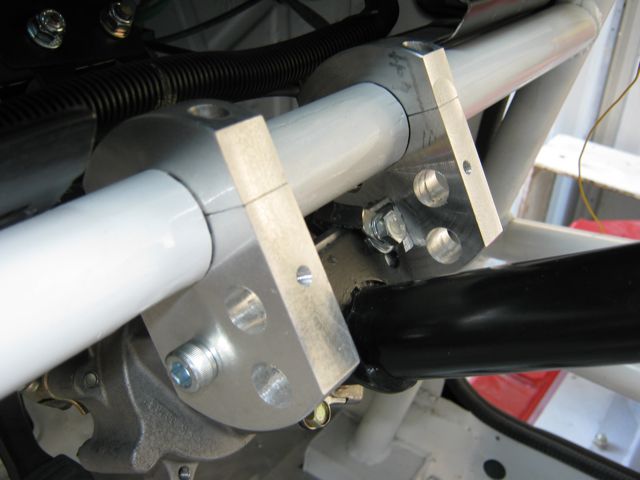
I haven't updated the build thread for quite a while due to lack of motivation to work on the car because it has been very hot here but I have managed to do some things on the rare cooler days starting with sorting the steering column out.
I had to move the column mount on the roll cage towards the centre of the car when I put the engine in to get more clearance for the exhaust. Unfortunately I didn't check this with the seat in place. Later when I put the seat in and sat in it it became obvious that I had moved the column too far as the steering wheel was offset to the left. There was no way I could live with this so needed to fix it which meant cutting the mount off the dash bar again
After more
To do this I needed another universal joint in the column and a self centring bearing on the firewall. After much searching on the internet I found a suitable bearing ( there were plenty of 20mm bearings but a 3/4in one to fit the column was hard to find).
The photos show how it was done
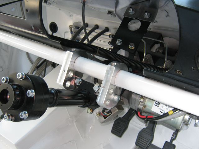
When I was searching for a suitable firewall bearing I came across a bracket that was designed to clamp a steering column to the dash bar.
I thought this was very good idea so I got my machinist to make me something similar that would suit my application.
The good thing about this is that it allows the steering wheel to be easily positioned exactly where I want it and it also makes the wheel square with the seat not at an angle as with the standard column.
Finished with a piece of trim.
Lovely work mate, very neat indeed
http://escort.accelerator.org
1968 MK1 Escort 1300GT
1969 'Big Wing' MK1 Escort
1972 MK3 Cortina 1600XL
1984 Sierra XR4i
And other junk I don't like to talk about!
Yeh it turned out really well, I just wish I had known/thought about a clamp mount in the first place
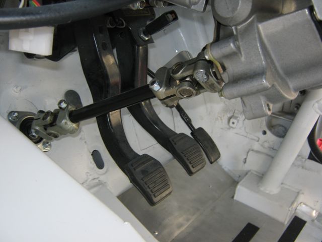
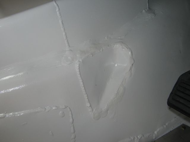
I needed a clutch footrest and normally I would have made a bracket to go on the tunnel but because it is an auto tunnel there is very little room between the pedal and the tunnel so I have stolen an idea that Gary had on one of his threads.
That is a cut out in the tunnel.
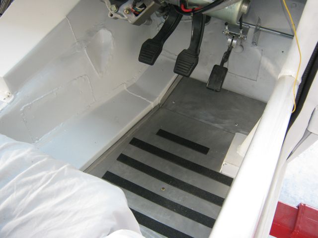
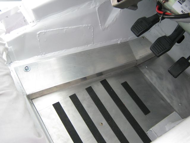
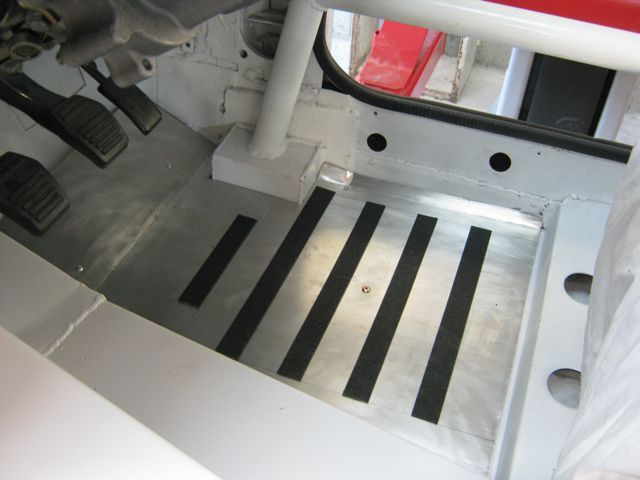
Next up I made some ally footwell plates.
My mate as something similar on his BMW but when you get in your foot slides along the smooth ally surface so I stuck some strips of 80 grit wet and dry on mine to prevent this.
Good to see things are happening again. My popcorn was going stale! I love this build - the attention to detail is amazing.
Great work.
Cheers
Matt
Good see back on track love the updates on this
Sorry about that
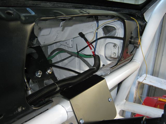
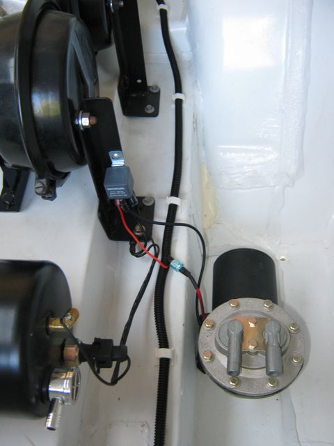
I have begun to do some wiring.
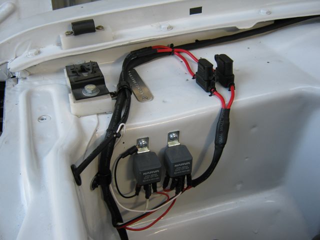
Started with the easy bit. These are the relays for the lights and electric fan.
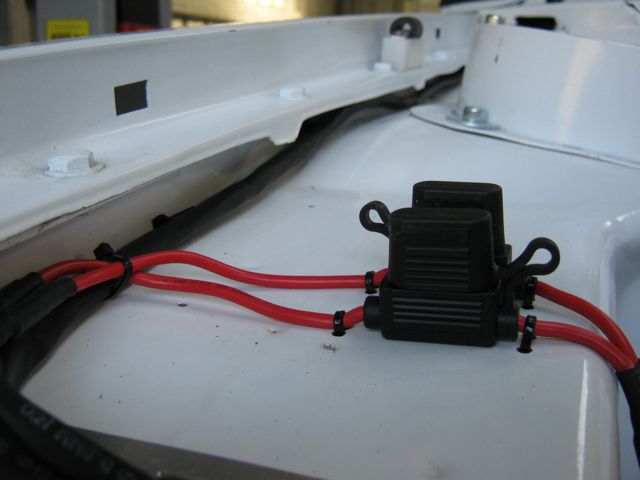
Fuse holders for the lights and fan
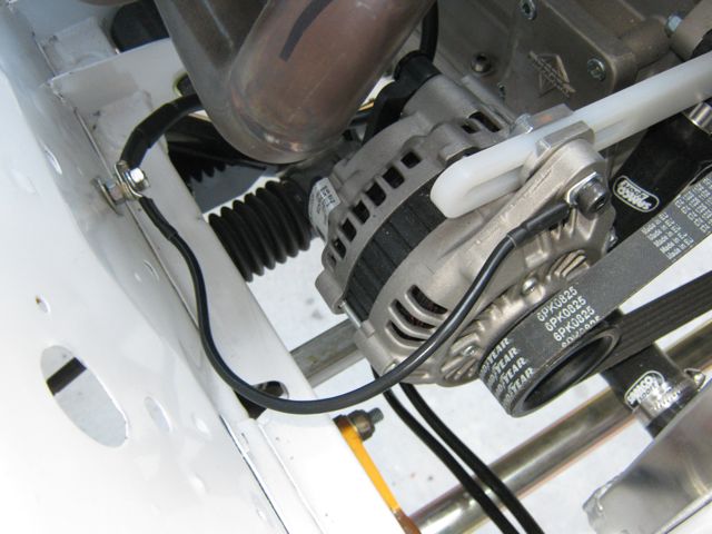
The alternator needs a separate earth because of the nylon adjusting bar. The engine earth is attached here also.
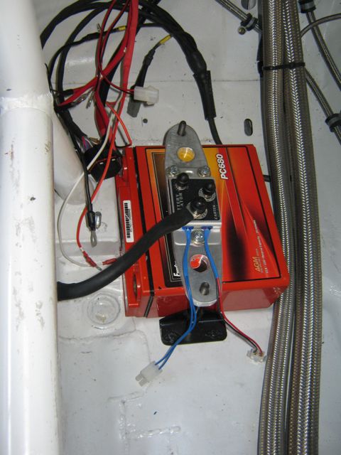
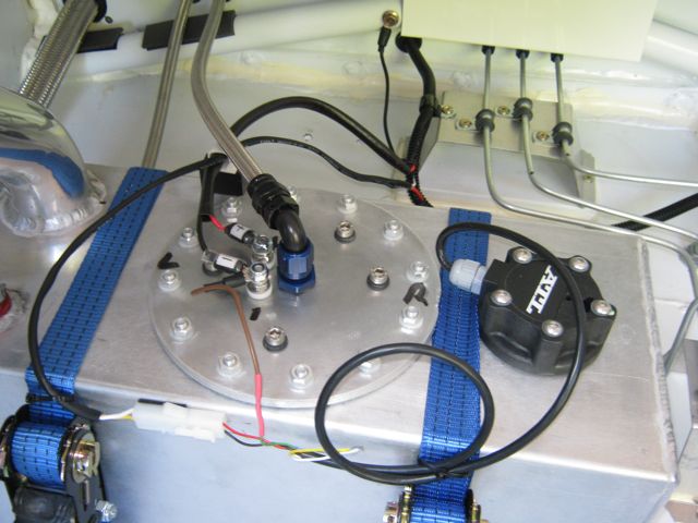
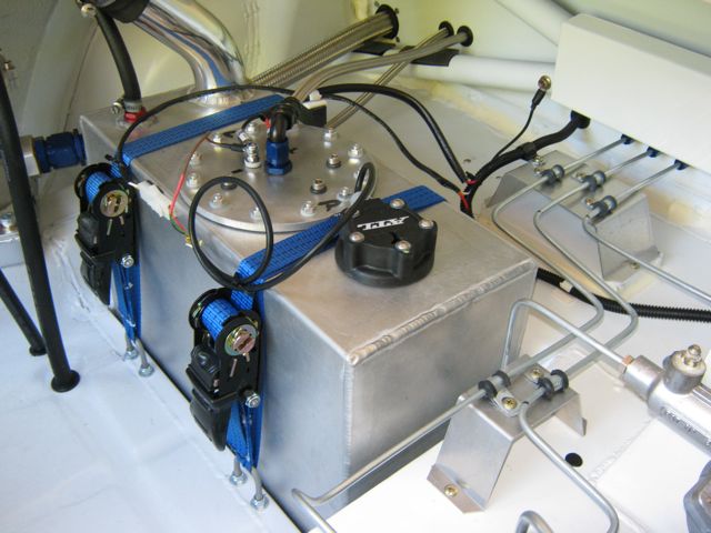
This will be the only wiring in the engine bay apart from the engine loom. I have relocated the battery into the cockpit.... more on that later.
The battery was supposed to be mounted in the in the cut out I made in the LH inner front wing but of course there are difficulties.
First there wasn't enough clearance for the tyre on full bump so I would have had to raise the battery a bit but when I came to do the wiring I didn't like how it all would be crammed in with the oil filter mount and the fuel pressure regulator so the battery is now mounted in the cockpit under the shelf for the ECU etc.
I have cut a bit out and Sikaflexed some ally in to give room for the tyre.
Battery inside.
Power steering control unit mounted.
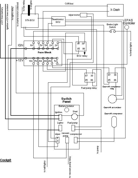
Because I have relocated the battery I had to revise the wiring diagrams....gave me something to do when it was too hot to be in the shed.
I have also changed the switch layout and added the wiring for the fuel level sender which I had forgotten.
More progress on the wiring.
This is the alternator main feed, external battery kill switch circuit and the control circuits for the lights and fan. The yellow wire is for the alternator warning light.
nice progress
and mods there
DS RESTOS
Well there is good news and bad news.
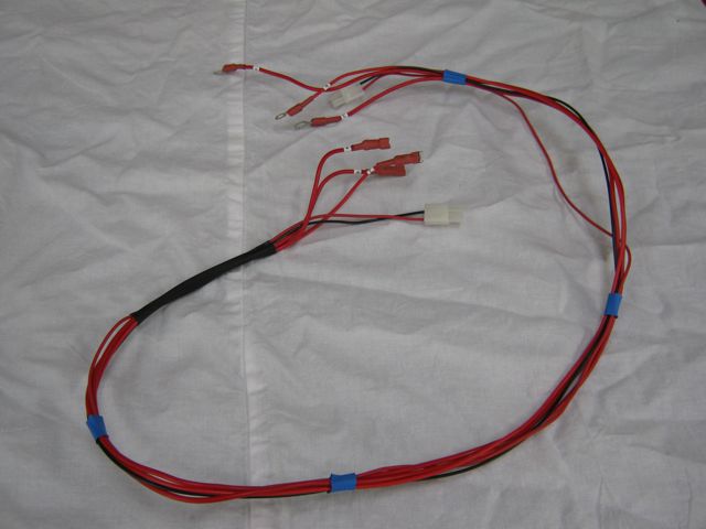
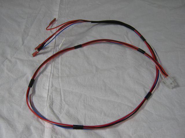
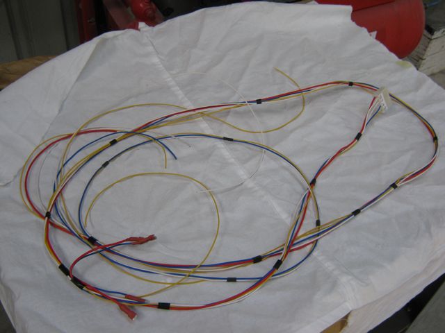
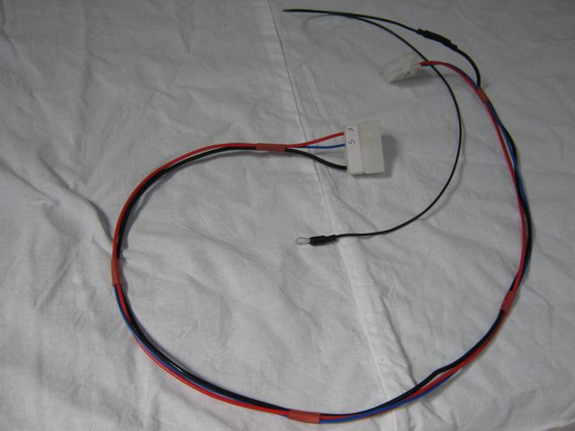
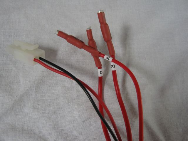
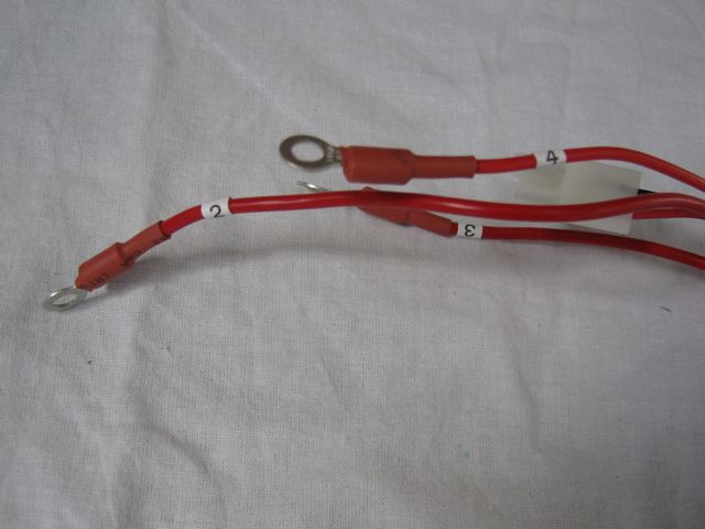
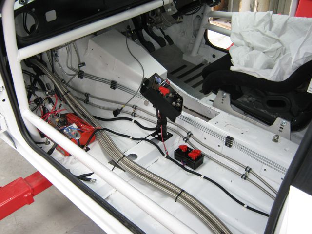
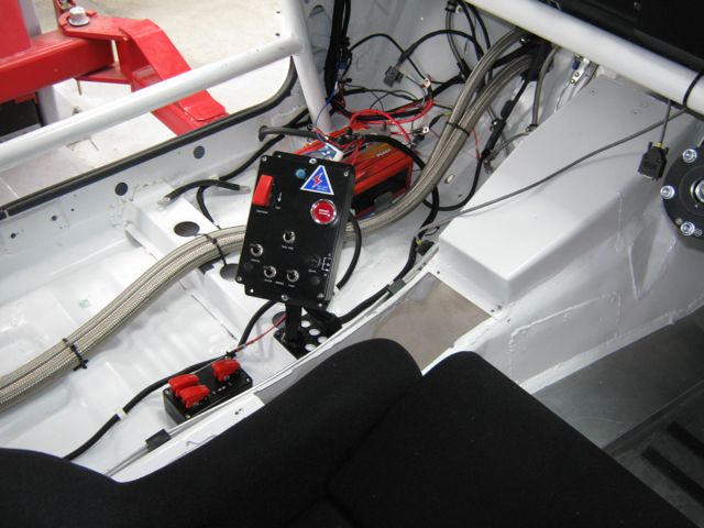
First the good...I have cracked on and made the wiring looms to connect things in the cockpit and the boot.
These two connect the switch panel to the "shelf'
This connects the "shelf" to everything in the boot via three switches to isolate the fuel pump, vacuum pump and paddle shift compressor.
this is for the wiper motor
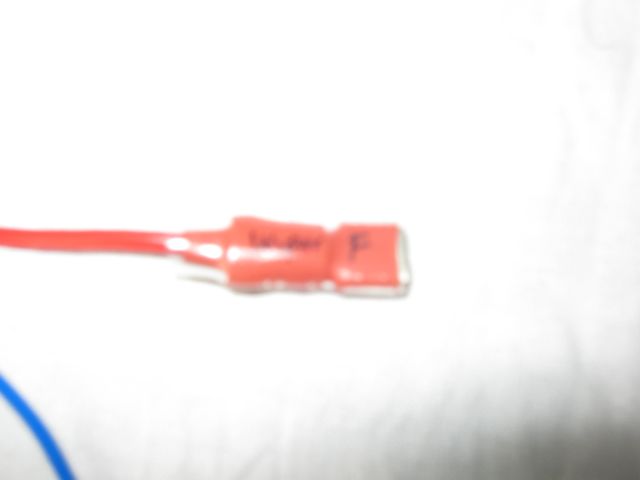
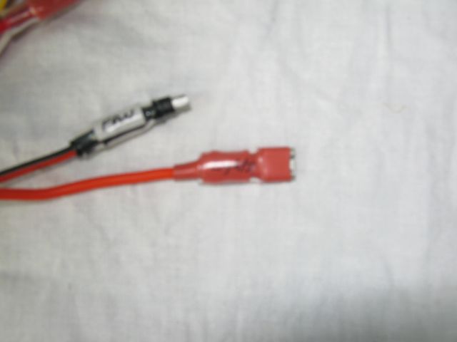
I have only used a a small number of different coloured wire so where I have used the same colour wire in a loom I have number tags on each end.
I have also "tagged" the terminations in felt pen and covered them with clear heat shrink to protect the writing.
Sorry about the crap photos
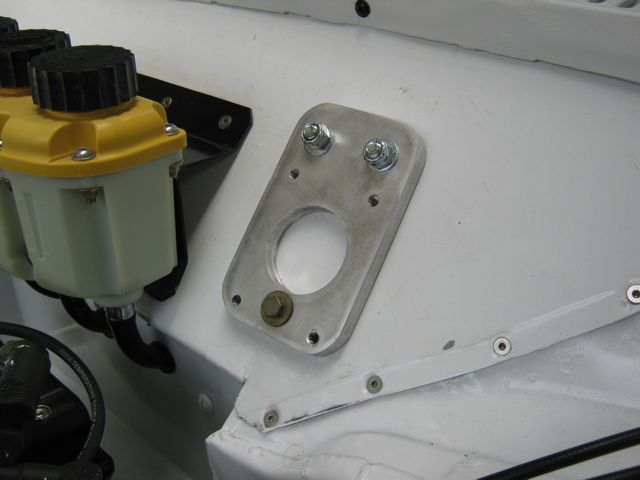
I have mounted the power steering control in a box so that I can reach it when belted in
Now the bad news....
I have had pain in my left shoulder and arm for a few weeks so I eventually went to my doctor who diagnosed a rotator cuff injury in my shoulder which has been confirmed with an ultrasound today.
Going back tomorrow for a cortisone injection and have been told to rest my shoulder until it gets better
My doctor says the injury has been caused by too much overhead work on the car.
So it looks like I will have to stop work on it for a while.... but knowing me I probably won't be able to resist doing a little bit on it
Sorry to hear about the shoulder injury
My missus had surgery to correct a torn rotator cuff cartilage, she did put up with it for about 5 years beforehand though!
http://escort.accelerator.org
1968 MK1 Escort 1300GT
1969 'Big Wing' MK1 Escort
1972 MK3 Cortina 1600XL
1984 Sierra XR4i
And other junk I don't like to talk about!
How did she put up with it for 5 years???? After a month I could not put up with the pain.
Had the cortisone injection yesterday and been told to rest it for 48 hours and I think I will rest it a bit longer..... I don't want to have surgery
The injury was very painful initially, but it did ease off with time. It was a constant weak point and niggle till she got it sorted properly.
http://escort.accelerator.org
1968 MK1 Escort 1300GT
1969 'Big Wing' MK1 Escort
1972 MK3 Cortina 1600XL
1984 Sierra XR4i
And other junk I don't like to talk about!
Well the cortisone injection hasn't fixed my shoulder so it is back to the doctor on Friday
Have tried to stop work on the car but got bored so I have done a bit more wiring while at the same time trying to rest my left shoulder.... not easy to do.
Wiring for the fuel pump and fuel level sensor.
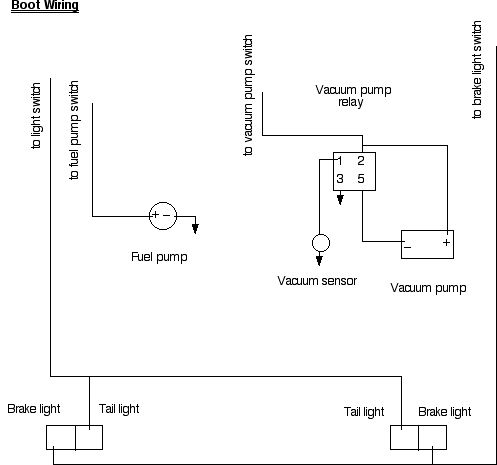
Vacuum pump wiring. The loom continues to the tail and brake lights.
The vacuum tank at the bottom of the photo has a sensor to switch the pump on and off depending on the amount of vacuum in the tank.
I have been moving on with the electrics and still trying to rest my shoulder. My doctor says to try another cortisone injection.
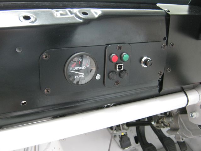
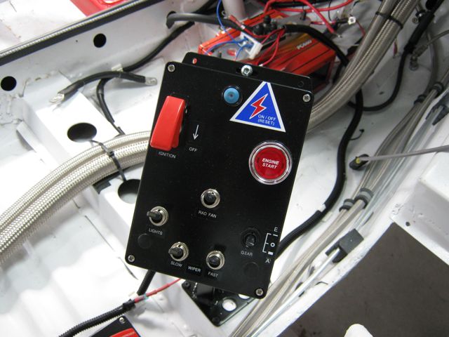
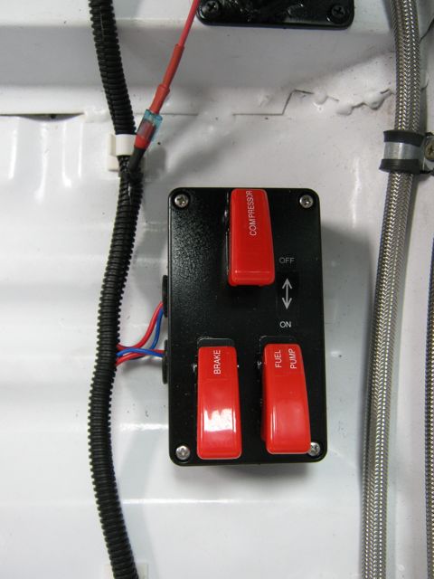
I have mounted 2 switch panels that are easy to reach belted in.
This one has all the controls that will be needed most.
This has switches to isolate the fuel pump, vacuum pump and compressor.
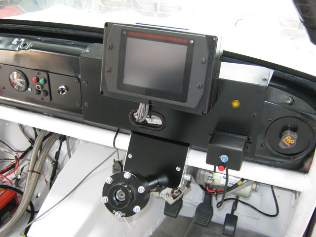
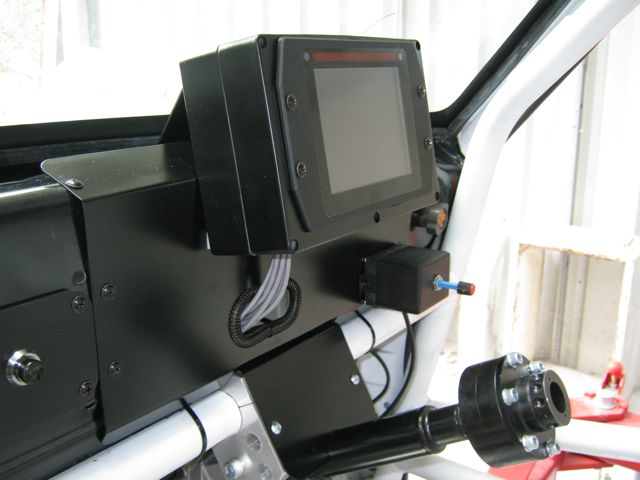
I have mounted the X-Dash just high enough so that the display is not hidden by the steering wheel.
I was going to use X-Dash to display the fuel level but the sender I have is a resistance one and the dash needs a voltage sender so I will use the fuel gauge I bought when I didn't know I going to get the X-Dash.
The panel with the 4 switches controls the displays on the dash and the black switch is for the launch control.... if I can figure out how to make it work.
http://escort.accelerator.org
1968 MK1 Escort 1300GT
1969 'Big Wing' MK1 Escort
1972 MK3 Cortina 1600XL
1984 Sierra XR4i
And other junk I don't like to talk about!
My mate John stores his race car in my shed and in return I get him to help out with my car.
So when he came around to get it on Sunday I got him to help me test the paddle shift gear actuator.
The first video shows changing down and the second changing up.
Of course it will be much quicker when it is controlled by the electronics not me
 Posting Permissions
 Reply With Quote


Bookmarks