


Indeed, Ball bearings can run almost zero oil pressure but his engine can't. He will not need an extra electric oil pump, the engine can and will supply what is needed.

Indeed, Ball bearings can run almost zero oil pressure but his engine can't. He will not need an extra electric oil pump, the engine can and will supply what is needed.
Yes it is a dual-ball bearing unit. Good to hear. I'll start with a 0.04"/1mm restrictor as Garrett recommends and progress as planned. I'm planning to rig a temporary in-line oil pressure gauge to confirm its in a good pressure range once I'm closer to to the first start up to have some piece of mind, but glad its not a disaster in planning from the start.
Last edited by blastronaught; 14-09-2020 at 14:18. Reason: additional clarification that its a ball-bearing
Slow progress on car, but new house and new job are quite distracting. Good news is new house comes with an awesome garage which should make progress a little easier. Anyway, mocking up turbo manifold and turbo placement now. Had to re-design the radiator bracket to slide it as far to the drivers side and forward as possible to make some more room. See pictures below with the left half of the manifold taped together for mock up. I'll weld a turbo flange on the front of the manifold for mounting somewhere around the location in pic2. Is it a bad idea to have the turbo all the way on the cylinder 1 port rather than centered on the manifold? I don't think I have much of an option with this short and simple schedule 10 pipe design. Maybe I'm overthinking it, but I could imagine the exhaust pulses possibly creating high pressure/poor evacuation of exhaust gas for the neighboring cylinders, but I also understand (or think I understand) that pulse tuning stuff doesn't apply as much with turbo applications.
Also, any limit on how far past the 1-port I can go past? I'm trying to hit that opening between the alternator and starter with the downpipe (pic3). To do that I'm eyeballing an adapter for the downpipe to go from the turbo's 5-bolt to a v-band, but I think it is going to be tight to clear the radiator with the extra length that brings with it. Through better planning, I probably could have gotten a housing with a v-band already on it but oh well. I'm also still searching for a 5-bolt downpipe that already has the orientation I'm looking for, but I'm nervous about the lack of flexibility during installation with that option.

Pulse tuning does apply to turbo's equally as NA engines but how important it is depends on what you are shooting for! A simple low boost cooking install won't be fussed with pulse tuning, a high output then I'd say it was critical. But from what I can see of your manifold, that isn't good is the use of Tee's! They will promote cross flow and not flow towards the turbo - you need to use swept bends to direct flow in one direction much more important than worrying about pulse tuning.
Hmm, I see what you mean Katana. Any ideas on better design or part to use in place of the tee? Maybe straight tube cut at a 45 degree to weld to the flange and the other side coped to mate into another straight tube segment for the "log" portion? Wouldn't be a smooth transition but probably better than dead-ending in the tee. I'm also trying to think of a way to incorporate additional 90 degree elbows for the two center ports, but cant see how they could mate to the log without complex geometry cuts. I don't have any coping jigs, and once I'm getting into that space maybe I should move away from the "easy" schedule 10 pipe route.
I imagine if the turbo was centered over the tee's this design would probably be fine.
On second thought, a 45 deg cut on straight pipe wouldn't mate with the circles in the flange so not a good option. Forgot my conic sections for second.
You're overly complicating things for yourself. Mount the turbo where ever it fits.
Making sure that you can get exhaust to and away from the turbo, piping to intercooler, cooling lines, oil drain and that the turbine housing is not to close to anything that can melt is more important than pulse tuning.
You should be able to find from a larger hardware store weldable 90 deg pipe bends. for your application 1 1/4" or 1 1/2". Should be quite cheap.
Get some for spares, from a 90 you can cut any angle you need. Eyeball cut and trim with an angle grinder to fit, no jigs needed.
You dont have to keep in 2 dimensional, take one port above the others, one below, one further from the head and by the turbine housing merge all to one 2"? bend.
Google how other people have made turbo manifolds for transversely mounted engines, im sure you can find some inspiration.
I dont think there are v-band turbine housings with integrated wastegates, so nothing you could have done about that.
Last edited by laur; 08-06-2021 at 18:20.
2x 82' Capri
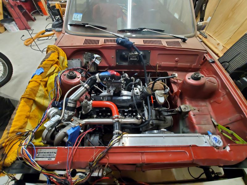
Been a while since I've updated this but I promise this is progressing... just slowly. Landed on this final design, I'm thankful for the input and I think the end product is better for it. Googling around, I haven't seen anyone run the runners upwards but this allows for the packaging I'm working with. Welding the transition from the circular pipe to the square hole in the turbo flange was interesting, and a fun challenge. Now working on the downpipe, going with 3". Sure there are plenty of opinions about that, but that seems to have the best availability for transitions and flanges (for example the v-band adapter from the 5 bolt turbo pattern in the overhead photo).

Also got around to making the adapter plate for the Solex carb to the Ford intake manifold. I don't have a mill, so made this with a metal band saw and a carbide burr in a dremel. Used a keensert to try to strengthen the two threads for mounting the carb. Its just a simple hole the same size as in the carb now. Eventually I'm planning on opening it up and tapering down into a square hole to match what is on the intake manifold for better flow. I've got some questions about where all the barb fittings go, I'll follow up with some more pictures soon to make things clear.
Now that the carb is mounted, I've got some questions about where the barb fittings all route to. I'll take some pictures and post soon to make that conversation more clear. So I'll see you guys soon.
Last edited by blastronaught; 04-12-2021 at 00:43.
Also got around to making the adapter plate for the Solex carb to the Ford intake manifold. I don't have a mill, so made this with a metal band saw and a carbide burr in a dremel. Used a keensert to try to strengthen the two threads for mounting the carb. Its just a simple hole the same size as in the carb now. Eventually I'm planning on opening it up and tapering down into a square hole to match what is on the intake manifold for better flow. I've got some questions about where all the barb fittings go, I'll follow up with some more pictures soon to make things clear.
Attachment 87570
Now that the carb is mounted, I've got some questions about where the barb fittings all route to. I'll take some pictures and post soon to make that conversation more clear. So I'll see you guys soon.
The revised manifold looks much better - its simple yet the flow paths look proper so i'm sure it'll work well. If the material is mild steel, go over your welds to ensure they are strong and (if it was me) I wouldn't wrap the manifold with wrap as I believe the intense heat retention whilst good for the turbo response is bad for steel longevity and crack resistance. You do have the advantage of not hanging the turbo's weight on the manifold otherwise i'd advise additional pipe bracing and maybe a hanger off the block to carry the turbo weight! Good project and progressing nicely - carry on!
opening the base up to match the manifold probably wont do anything, lets not forget you are blowing air through it, so better to leave as is, leaving more material in your adapter is good to be a good thing anywayOriginally Posted by blastronaught
Thanks katana. The turbo is just hanging off the mani right now, but I'm planning on supporting it as you mentioned.
Graham, I was thinking to open up the flow path because as it is the flow dead ends abruptly in the intake manifold and has to make a 90 degree turn to head into the intake runners. Strength was a concern too though. I'll keep it as is, and down the road I may experiment with it some more. Good enough for proof of concept, and if the engine doesnt wreck itself I'll put some more time into optimizing this sort of thing.
On to some carb plumbing questions. Correct me where I'm wrong here, some of these are pure guesses:
1) No idea what this one is?
2) Run to the snorkel/ boost pressure reference at #4?
3) ? Brake booster/PCV valve?
4) Run to #2 as boost pressure reference? Also maybe T off into the boost pressure reference from the Renault 5GT FPR.
5) run to #7 boost pressure ref
6) Fuel from the FPR
7) run to #5 boost pressure ref
8) coolant (feed in or return out? does it matter?)
9) coolant (feed in or return out? does it matter?)
Any Solex experts on here that can help out with that plumbing?
Another question today: stock valve stem-to-rocker clearance per factory manual is 0.010" intake and 0.021" exhaust (0.25/0.53mm). For this turbo application, should I open up the exhaust clearance for the extra heat?
coolant pipes 8, 9 flow direction doesnt matter, although i really doubt you need to connect them.
opening up teh tappet clearance will have a negligible effect on valve temp.
Looking great, I love carburetor turbo engines (I guess I'm getting old)
Not trying to keep the valves cooler, but with the extra heat there will be extra thermal expansion. Wasn't sure if it is enough extra expansion to warrant opening the clearance to avoid a valve no fully closing and perhaps burning.
extra expansion will be negligible, especially as the head will also expand. exhaust valve clearances are pretty huge in the first place. run too big and you will be missing the closing ramp on the cam which increases mechanical stress on valve and seat, not to mention tappet noise
Correct, use stronger springs if possible to stay safe. Check valve clearance more often as you would normally and all fine.
Wow, has it really been 7 months since I posted on here? Well, I'm inching closer to initial start up, just to see if it can idle without spilling fluids or otherwise destroying itself. Coolant is pretty much set, need to put the heater core back in and connect it; no coolant to the turbo for the time being. Exhaust is complete up to the downpipe (not in photo). Intake complete other than the filter assembly (TBD); no BOV yet. Electrical harness is thrown in plugged in to engine components; confirmed it can still turn over. The last thing to figure out is fuel, which I plan on working on this week. Any experience from anyone on my previous post about the barb fittings on the carb? Particularly #1 and #7.#2 I found out is just atmosphere pressure reference. One concern is the proximity of the downpipe to the back of the alternator, maybe only 2 or 3cm. The alt has some plastic electrical components on the back too, so may have to source a smaller one or one with a different electrical layout. Planning on running a mobile ham radio, so maybe a bit more modern/efficient alternator wouldn't be a bad idea anyway.
 Posting Permissions
 Reply With Quote

Bookmarks