User Tag List

+ Reply to Thread
Results 1 to 18 of 18

Thread: Alternator wiring

  1. #1
    Spanner Monkey Kmp's Avatar

    Join Date
    Feb 2009
    Location
    Burnham on sea
    Age
    39
    Posts
    390
    Thanks
    53
    Thanked 8 Times in 6 Posts

    Alternator wiring

    Hi all,

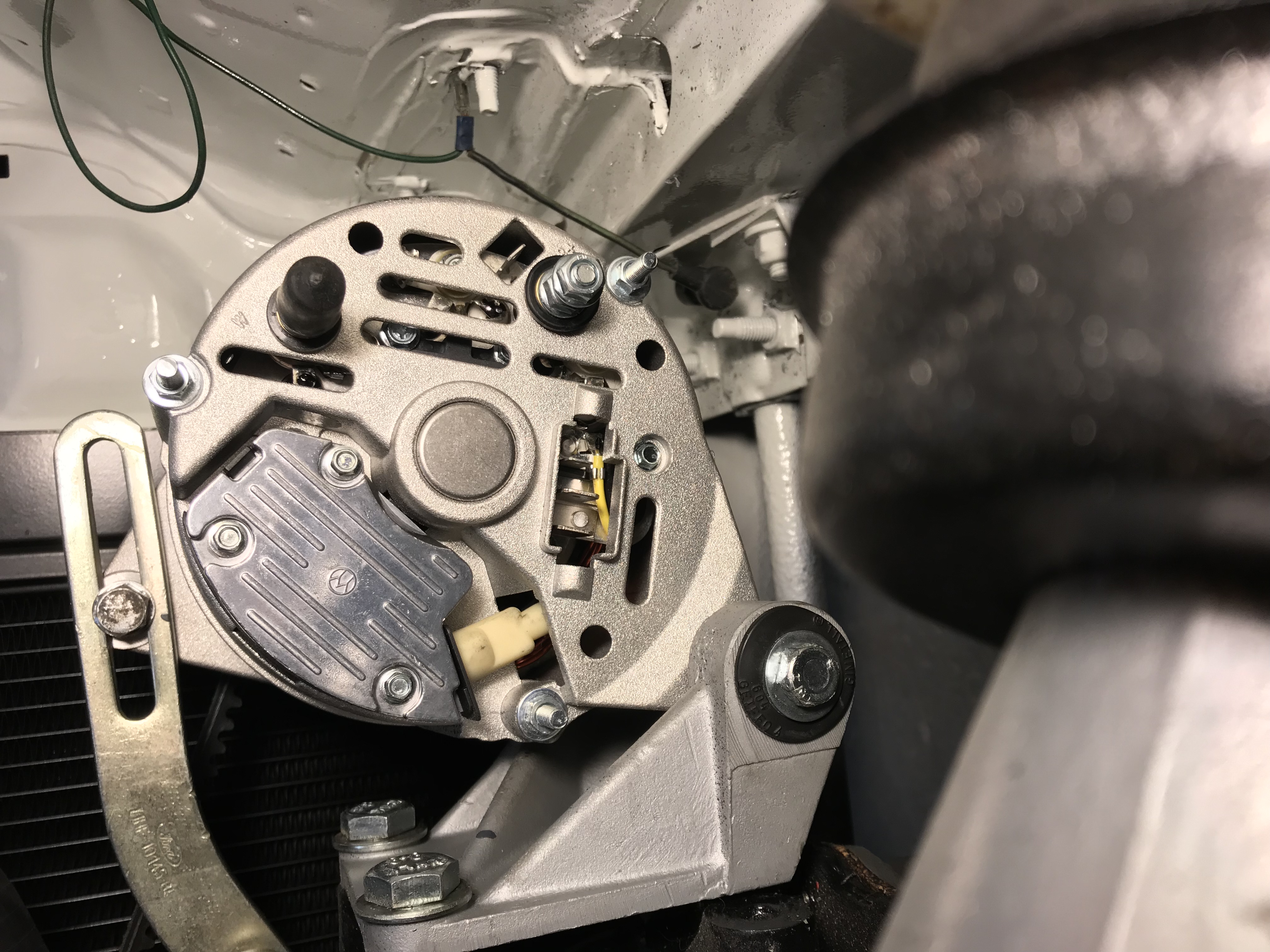
    i have recently purchased a rotek alternator as it fits the Ford 3 pin plug, how ever it has a few
    more connections on it and I don’t know how to wire it. I have changed from a crossflow to a pinto so need to change the wiring, but googling it I can’t find out what connections are actually for what.

    The instructions are useless as there is no wiring information on them.

    could anyone please tell me what wires need to go where? I can find info on Bosch and Lucas ones but not for what i have.

    How well does it work to send the output (battery charging cable) through the starter motor cable? When I have been searching previous posts I see that some have done this.

    thanks
    kris


  2. #2
    TURBOSPORT SPONSOR Turbosport Subscriber
    Turbosport Moderator
    Turbosport Administrator
    Graham's Avatar
    My Race Car
    My 1st Project
    Join Date
    Feb 2006
    Location
    Ely, Cambs
    Age
    56
    Posts
    25,113
    Thanks
    310
    Thanked 2,476 Times in 2,250 Posts

    Re: Alternator wiring

    the alternator plug you have there will plug straight into the alternator.

    its common to connect the main charge lead from the alternator to the main starter feed cable, lots of car manufacturers do it, it saves on wire!

  3. #3
    Spanner Monkey Kmp's Avatar

    Join Date
    Feb 2009
    Location
    Burnham on sea
    Age
    39
    Posts
    390
    Thanks
    53
    Thanked 8 Times in 6 Posts

    Re: Alternator wiring

    So just to check, the centre wire in the 3 pin plug which is the old large ish red cable is fine to be connected as it was into the centre connector of the alternator?

    Does it need to be earthed?

  4. #4
    Racer Decade Plus User

    Join Date
    May 2012
    Location
    Camberley, Surrey
    Posts
    3,241
    Thanks
    5
    Thanked 356 Times in 341 Posts

    Re: Alternator wiring

    Quote Originally Posted by Kmp View Post
    So just to check, the centre wire in the 3 pin plug which is the old large ish red cable is fine to be connected as it was into the centre connector of the alternator?

    Does it need to be earthed?
    The body of the alt. is earthed through the mounting to the engine.

  5. #5
    TURBOSPORT SPONSOR Turbosport Subscriber
    Turbosport Moderator
    Turbosport Administrator
    Graham's Avatar
    My Race Car
    My 1st Project
    Join Date
    Feb 2006
    Location
    Ely, Cambs
    Age
    56
    Posts
    25,113
    Thanks
    310
    Thanked 2,476 Times in 2,250 Posts

    Re: Alternator wiring

    Quote Originally Posted by katana View Post
    The body of the alt. is earthed through the mounting to the engine.
    its is, but if you have proper mk2 RS2000 alternator bracket and adjuster you should add an earth because they are rubber bushed so insulate the alternator

  6. The Following User Says Thank You to Graham For This Useful Post:

    Kmp

  7. #6
    Spanner Monkey Kmp's Avatar

    Join Date
    Feb 2009
    Location
    Burnham on sea
    Age
    39
    Posts
    390
    Thanks
    53
    Thanked 8 Times in 6 Posts

    Re: Alternator wiring

    Yeah it is an rs2000 one so will earth it separately, thankyou for your help

  8. #7
    Pole Position Decade Plus User
    Turbosport Administrator
    Miniliteman's Avatar

    Join Date
    Feb 2004
    Location
    the Netherlands
    Posts
    4,889
    Thanks
    38
    Thanked 611 Times in 558 Posts

    Re: Alternator wiring

    On a std RS2000 the alternator is earthed through the adjuster-bracket.
    Within the 3 pin plug the 2 bigger pins are connected inside the alternator; there will be 2 thick red wires that run in parallel to the battery + . The 3rd smaller pin is for the charging light on the dash.
    On some alternators there is a separate B+ terminal where you can fit a suppressor (condensor) to. And a W+ terminal which can be used for tach-reading on diesel engines and/or the electric heater element on a carb.

  9. The Following User Says Thank You to Miniliteman For This Useful Post:

    Kmp

  10. #8
    Spanner Monkey Kmp's Avatar

    Join Date
    Feb 2009
    Location
    Burnham on sea
    Age
    39
    Posts
    390
    Thanks
    53
    Thanked 8 Times in 6 Posts

    Re: Alternator wiring

    Excellent, thankyou for explaining it all, that clears it all up perfectly, it will be earthed through the adjuster bracket as you say, so that’s easy.

    Thanks
    Kris

  11. #9
    Pit Crew Decade Plus User GavinR's Avatar
    My Race Car
    My 1st Project
    Join Date
    Jun 2004
    Location
    Bristol
    Age
    53
    Posts
    1,494
    Thanks
    18
    Thanked 118 Times in 103 Posts

    Re: Alternator wiring

    Hi Kris,

    If there is only one big red wire going to the alternator plug (as it looks in your picture), you should run another red cable of a similar size to the other large terminal hole so the current from the alternator is carried through 2 wires not just one.
    Also, it is a good idea to insulate / cover / tape the B+ terminal that is not used as this is live when the engine is running.

    Thanks
    Gavin
    GavinR

    http://www.turbosport.co.uk/signaturepics/sigpic2999_8.gif

  12. The Following User Says Thank You to GavinR For This Useful Post:

    Kmp

  13. #10
    Spanner Monkey

    Join Date
    Apr 2011
    Location
    north wales
    Posts
    260
    Thanks
    0
    Thanked 11 Times in 10 Posts

    Re: Alternator wiring

    Hi,

    The B+ terminal should be live all the time, not just when the engine is running, the alternator is always across the battery, as the output is not switched.

  14. The Following User Says Thank You to caprimk1v4 For This Useful Post:


  15. #11
    Tyre Kicker

    Join Date
    Mar 2020
    Location
    Edinburgh
    Posts
    37
    Thanks
    3
    Thanked 1 Time in 1 Post

    Re: Alternator wiring

    Apologies for regurgitating this old thread but would like help on this item for a Pinto.
    I have changed my burned our loom to a new Xflow loom and am about to extends the alternator wiring etc but I I have only two wires (a thick red & smaller blue) going to the alternator plug. I have untapped the old loom which has been well butchered in the past and see that someone has soldered in two red wires into the single red wire that feeds to the alternator. Is this really necessary as if I've read this right the pins inside the alternator are linked. It just seems odd if its not totally necessary. As always your assistance is greatly received.

  16. #12
    Pole Position Decade Plus User
    Turbosport Administrator
    Miniliteman's Avatar

    Join Date
    Feb 2004
    Location
    the Netherlands
    Posts
    4,889
    Thanks
    38
    Thanked 611 Times in 558 Posts

    Re: Alternator wiring

    The two wires are there to share the amperage from the alternator. 45 or even more Amps is a too much for a single wire. Also, I never solder wires unless it's for very low amp connections for a sensor for example.

    PS: why did the old loom burn out?

  17. #13
    Tyre Kicker

    Join Date
    Mar 2020
    Location
    Edinburgh
    Posts
    37
    Thanks
    3
    Thanked 1 Time in 1 Post

    Re: Alternator wiring

    Hi, thanks for your reply.
    So I will connect two reds to the single red further up the loom then extend them including the blue wire to reach the alternator, I can use the old plus which had three pins.
    As we speak I’m pulling back the loom tape to te exit the coil feed from the main loom and come across another double insulated with criimped to the black & yellow coil wire? Why would that be, it looks like a factory crimp.

  18. #14
    Tyre Kicker

    Join Date
    Mar 2020
    Location
    Edinburgh
    Posts
    37
    Thanks
    3
    Thanked 1 Time in 1 Post

    Re: Alternator wiring


  19. #15
    Pole Position Decade Plus User
    Turbosport Administrator
    Miniliteman's Avatar

    Join Date
    Feb 2004
    Location
    the Netherlands
    Posts
    4,889
    Thanks
    38
    Thanked 611 Times in 558 Posts

    Re: Alternator wiring

    The wire (grey insulation?) is the resistor-wire for the coil. During normal operation this wire is in series with the OEM coil to limit the current through the coil. When starting, this wire is bypassed via a terminal on the OEM startermotor so you get the full voltage onto the coil for better spark (voltage drops during starting) and better starting. If you have an electronic ignition then most likely it will need a full +12 Volts all the time so the resistor wire should be removed or bypassed. I made a how-to in the "how to fit electronic ignition" sticky-thread.

  20. #16
    Tyre Kicker

    Join Date
    Mar 2020
    Location
    Edinburgh
    Posts
    37
    Thanks
    3
    Thanked 1 Time in 1 Post

    Re: Alternator wiring

    Top man, thanks for sharing your knowledge, I will be running electronic ignition so will look up the bypass sticky ��

  21. #17
    Bodger

    Join Date
    Apr 2005
    Location
    England
    Age
    60
    Posts
    54
    Thanks
    1
    Thanked 2 Times in 2 Posts

    Re: Alternator wiring

    Miniliteman "how to fit electronic ignition" sticky-thread, Leon I've trawled through the entire site several times, please give me a clue where this article is you have kindly written as I'd love to read it

  22. #18
    Pole Position Decade Plus User
    Turbosport Administrator
    Miniliteman's Avatar

    Join Date
    Feb 2004
    Location
    the Netherlands
    Posts
    4,889
    Thanks
    38
    Thanked 611 Times in 558 Posts

    Re: Alternator wiring


+ Reply to Thread

Bookmarks

Posting Permissions

  • You may not post new threads
  • You may not post replies
  • You may not post attachments
  • You may not edit your posts