


Originally Posted by bytesandbolts
Hi Bud
I Pm'd you about a Mk1 Escort dash wiring loom connector.
Emailed you on your blog site too, got no answer from either.
Cheers
Rob

Hi Bud
I Pm'd you about a Mk1 Escort dash wiring loom connector.
Emailed you on your blog site too, got no answer from either.
Cheers
Rob
Last edited by rallyrob; 26-08-2020 at 17:55.
Ive just sent you a reply back to your email Rob, apologies for the delay.
Mk1 Escort 1.3 XFlow Turbo - http://bytesandbolts.com/tag/mk1-escort/
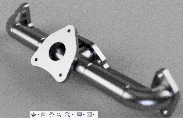
Made some progress with the turbo manifold, thought I'd post a brief update.
Scanned in a set of gaskets and created a modified drawing that includes a crossbar connecting all 3 gaskets together, as well as a flange for the EcoBoost turbo. Had a few copies of each cut from 10mm stainless steel. I may use the exhaust flange drawing to get some copper gaskets cut also.
Made a heatsink block to help minimise warping when welding, which also includes argon inlets to backpurge the stainless whilst welding.
Running the 2nd line from the argon bottle to backpurge.
Eye ball measurements to gauge turbo clearances. Note this is the mk2, the turbo setup isn't for this car or engine.
Measuring the old turbo setup for clearance dimensions. I don't have the mk1 with me atm that the engine and turbo will drop into for measurements, so using the old turbo setup as a rough guide, plus old photos, plus measurements taken from the mk2 engine bay that I do have with me.
Test fit flange to make still it still fits.
3D printed off one of the intersecting pieces to assist with positioning the pilot hole and holesaw.
Since starting this manifold I have come to realise how difficult stainless steel can be to cut (2 blunt bandsaw blades later).
Gotta yet tidy use and smooth out some of the insides with the Dremel.
Last step is to weld on the turbo flange itself which is what I'm working on atm now.
Mk1 Escort 1.3 XFlow Turbo - http://bytesandbolts.com/tag/mk1-escort/
Forgot to add some of the CAD snapshots.
Mk1 Escort 1.3 XFlow Turbo - http://bytesandbolts.com/tag/mk1-escort/
Looks good
Manifold is finished welding wise, still gotta tap and add the studs and maybe shape some of the ports more inside.
Made a heat block for the turbo flange to use whilst welding.
Outlet sticks out quite a bit, I think it will fit once in the engine bay, otherwise will be flipping the TIG to AC mode and working some magic on that also.
Comparison with the old turbo setup.

Mk1 Escort 1.3 XFlow Turbo - http://bytesandbolts.com/tag/mk1-escort/
I can't fault your welding fabrication but do see a potential problem with ex. flow from #1 and #4 and trying to persuade them to turn sharp 90+ deg. turn into the turbine - hot & fast moving gasses don't do sharp turns - liable to shoot straight across the junction! In fact, one of those pictures makes it look like the flow from 1 & 4 is directed into 2 & 3 ? ? ?
Nice work!! But like Katana says, I think flow from 1 and 4 will make a lot of pulsing interrupting 2 and 3. And if exhaustvalves overlap you will get cylinderfilling backwards? Nearly like a Miller cam.
Really like this project
Thank you, it was the welding aspect I was most concerned about, this was my first project working with stainless. I understand the concerns around the manifold design and I'm aware of it's drawbacks, however I was mostly concerned how I would handle the actual construction of such a manifold from scratch. This new stainless manifold is very similar to the old one I ran, with a couple minor improvements around cylinder 2+3 having separate runners compared to the original.
As mentioned in an earlier post I have a couple extra copies of the flanges at hand, and now the heatblocks are made, making another manifold would be quicker second time round and I would attempt individual equal length tubes going into a collector. I may end up running with the manifold I already have, but I have a lot of other aspects of the vehicle to work on so time will tell. All of this is very much experimental and I'm just working one things one piece at a time.
Mk1 Escort 1.3 XFlow Turbo - http://bytesandbolts.com/tag/mk1-escort/
This one works
Thanks for the share, cant believe I didnt think to do it that way! Deffo something to consider next time I put one together.
Mk1 Escort 1.3 XFlow Turbo - http://bytesandbolts.com/tag/mk1-escort/
Bit of faffing about but it more or less points the exhaust in the same direction, just takes up a bit more space
Yeah - but it'll flow an awful lot better - win win!
Billet plenum to replace our fabricated one. Should really get round to fitting it
That's lovely.
I shouldn't listen to the critics too much finding fault with your manifold design, it's always easy to be wise after the event.
Ford made a balls up with the design of a Cosworth 4x4 manifold but it was still good enough for them to use for many years on the Group A & N Sierra and Escorts, including winning the Monte. It was only when they introduced the Escort WRC than an improved cast manifold was fitted to their engines.
It's probably not as cool a way to do it, but the 'Ka era' valencia front timing cover has a cam position sensor - the cam sprocket chopper can't be that different to a 711M x/flow cam sprocket.
Sometimes what 'you' see as criticism is actually advice learnt through experience!
The critics I have come across in life are generally the ones that can't do the job themselves.
 Posting Permissions
 Reply With Quote
Bookmarks