


I have no idea why the same picture was posted 3 times. Sorry about that.

I have no idea why the same picture was posted 3 times. Sorry about that.
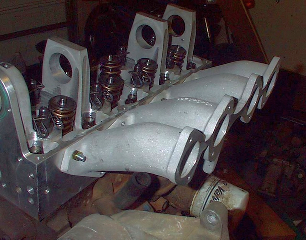
The port downdraft angle looks very nice, I hope it holds water for you, way better port angle than std
Will need a nice downdraft/large radius bend inlet manifold to match if you are using DCOE'sOriginally Posted by MemphisTwin
Like this:
"Horsepower sells cars, torque wins races" - Enzo Ferrari
looking good..how well did they seal...i cant see the guides in the pic ..did the tubes end before the guides .. after flow testing my downdraught head i ended up using a tapered port tube... from 41mm at gasket face to 37.5 mm at tube end just before guides...i ended up extending my tubes out of the head total tube length from valve guide to end was 100mm and used as the manifold...
keep us posted ..mark
The machining was very accurate, so the tubes were a great fit to the head. I used copious amounts of JB Weld on the casting and I'm pretty certain I've got a good seal on all ports. JB Weld is brilliant stuff as it remains extremely viscous for hours, meaning it runs into all nooks, gaps and crannies before setting as hard as cast iron.
The tubes go in just short of the valve guide. I originally intended to use Flatslide carbs (would still like to) a and have my eyes on a sett of Keihin FCR39 downdraughts which would mate to the head with a simple fabricated steel manifold. Allen's Performance have said that they can respace the carbs to suit the Pinto port spacing , and the price of carbs plus respacing ends up at about the same as a set of used 45DCOEs. I KNOW that the Keihins would be a better bet than the Webers (although both will work fine) but it really is experimental on jet sizes etc. The Weber option may be easier as it's all ancient technology and well documented., but I do like experimenting!
More soon.
My take on the carbs after having done some flow testing is that if you can get a decent size bike carb for this head it would certainly be better than 45's, But they need to have a 42mm throttle plate, R1's have a 40mm throttle plate and only flow the same as 45's with a 37mm choke, that simply is not enough flow for a pinto head, but if you can find a set of blackbird carbs or similar with 42mm throttle plates, space them out to pinto bore spacing, drill out the main jets considerably larger and tune from there, that would be a better option than 45's imho, and I actually believe that bike carbs can pull a lot more smoothly from low rpm/light to moderate throttle openings than webers, the reason is that the variable choke design alters the main jet vacuum signal strength where as webers and more on off, with the idle jet and progression holes trying to blend the idle with main jet operation, not the easiest thing to do from 2k upwards with large chokes
In terms of air flow 42mm bike carbs I am sure will flow plenty of air for a 1700 pinto, 40mm might even be ok but I would prefer 42's for better high rpm breathing, they will flow about as much air as a 45mm carb will with 40mm chokes or a little more I am sure, 48's / 50's flow a heck of a lot more air than 45's but 45's would be the ideal carb size for a 1700cc engine anyway
Another advantage of the bike carbs is the dead straight inlet ports, that will greatly help inlet ramming at and above peak torque, + you can use a longer inlet length than usual, around 400mm instead of 330mm off the top of my head which is much closer to an ideal length as used on many 16V engines
Have you tested the air flow of the head?
Looking forward to this build
"Horsepower sells cars, torque wins races" - Enzo Ferrari
The bike carbs I'm planning are smoothbore flat slide race carbs, not the diaphragm CV type. They are equipped with accelerator pumps and don't have butterfly throttle plates as the slide is lifted mechanically. The FCR39 has huge flow capability and would be perfect for my 1700. I used this type of carb on my old Mallock fitted with an ex-sidecar GP 1150cc Suzuki GSXR water cooler engine. Throttle response is incredible!
sounds great..fingers crossed...i used 1999 suzuki gsxr 750 injection throttle bodies ..46mm single butterfly and individual bodies.ideal for pinto spacing..ive gone with 8 injectors .4 after butterfly in throttle bodies and 4 top of velocity stack..my engine is a 2.2..long rod...i went with 46mm inlet and 37.5 exhauste ....i will try and find the flow test pics and data all done with stnd valves.... cheers mark
the first test head (or 1/3 ) being flow tested by tom..
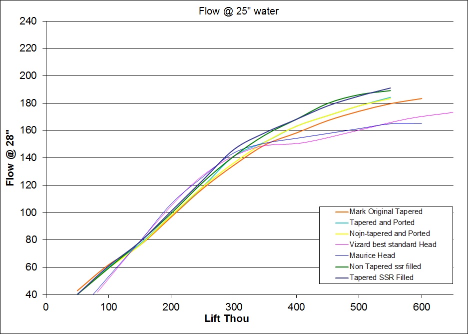
the results below
all results are with stnd valves..cheers mark
are they not 46mm inlet tapering to a 42mm butterfly ?
Thanks for posting that Mark. That's impressive flow from a standard 42mm inlet valve, equivalent to @ 119cfm at 10" at 0.5" lift and 17.5% more than Vizard managed. I'd like to see the results with the 46mm valve and ported to suit!
The butterfly measures 45.7mm and the inlet is 48.5mm only on the early 1999 itbs...there is enough meat on the opening to open up to 51mm safely..
cheers mark
yes....ive been mucking about with short side radius profiles....under the tap ect ..and ive ended up with a kind of vane design...laminer air over the top and forced air under neath...just for the short side ...cheers mark
I'm glad you've noted the use of Keihin FCR's as Mikuni RS's are not suitable for down draught usage. Beware with the FCR's as there are types suitable for side draught and for down draught and they don't swop (angle of float bowl casting is different) FCR's really are the Rolls Royce of Bike carbs so a very good choice but finding someone who a) has a chassis or engine dyno that b) understands tuning Keihin FCR's and c) has a shed loads of jets and needles for them maybe tricky!
Flatside's are the ultimate carb, my bro has a set of them on an old race bike, slide throttle, nothing in the air path whatsoever at WOT, have got to be more responsive for racing exiting corners than regular bike carbs for sure
The GSXR TB's are 42mm internal diameter at the exit, Hayabusa is 50mm ID down to 46 and then 42 at the exit which is a parallel bore, they flow a lot of air, more than 45's can flow with large chokes but they don't compare to 48's, but if they are mounted pretty close to the head then I believe they would flow enough air for any power you like from a 2.0, I would sooner a lot smaller trumpet ID, more like 45mm parallel ID trumpets with a small radius 270* flare would be ideal for a 2.0 monster, giving a stronger pulse signal, huge flared trumpets like Jenvey use are for show rather than making power imho
The guy from Sweden JP was using 45mm flatside's on some of his 250 to 258bhp engines, with a very small radius on the parallel trumpets and tapering down to 38mm or so over a long inlet length, all of which helps cylinder ramming at high rpm and maximizing pulse tuning strength, the longer inlet length also helped out I am sure and the 46mm inlets, 15.89mm valve lift, 145mm rods etc, I dare say those power figures are correct or darn near it because of such a well flowing head, inlet system, valvetrain, everything maxed out to the last, whatever about the figures it would beat most 2.0 16v engines on a rally stage
This build is getting interesting!
"Horsepower sells cars, torque wins races" - Enzo Ferrari
What method of machining did you use to bore for the inserts? Are they a press fit and then sealed with JB? Have you any pics of the process? It would be interesting to see.
Seems there are going to be a couple of downdraught monsters.
Shaun
2" or 3" adjustable boring head with carbide tip (a small carbide boring bar can be used with these, handy for boring accurate size holes on a milling machine)
3" boring head would be more solid for faster boring/larger cuts at a time
I presume the steel pipe is a press fit, I wonder if the head was bored, then fill in the roof of the port, finish cut the ports with filler in place and then press in the light wall pipe, mill the face carefully as not to turn the pipe (moving along X axis parallel with head rather than Y)
Would need to make a jig to get the port bore angle just right but once the angle and position is found it would be pretty easy after that
I would turn down a suitable size steel plumbing pipe made to fit each bore, press fit of 0.02mm should do the job nicely
As said the only thing I would be concerned abut is sealing the ports esp the port roofs, I imagine the ports in this head have only broken through at the port roof from the port entry to head the valve guides
For a 2.0 head if the ports were bored 38mm and only the roof was broken through I wonder if this area would be accessible with a mig or tig welder, a small mig welder head might just be able to weld in profiled "graft" of a 38mm ID x 4mm wall steel pipe if you get my drift, then the port floor could be milled and stuffed with an alloy plug bolted in place at the bottom of the port entry outside the water jacket, finally mill the port to 38mm ID, just a thought but if the welding was accessible this would result in a 100% water channel seal and MEGA POWER from a pinto, 230bhp with relative ease from 2.0
"Horsepower sells cars, torque wins races" - Enzo Ferrari
Like this:
"Horsepower sells cars, torque wins races" - Enzo Ferrari
What an alloy port floor stuffer looks like:
(Same process, boring head in a mill, turn down alloy stuffer semi machined to shape, press in and port to final shape)

Last edited by RWD fords rule; 19-01-2014 at 01:05.
"Horsepower sells cars, torque wins races" - Enzo Ferrari
I'm sorry, but I don't have any photos of the process. I'm not sure what machine was used to bore the holes, but probably a vertical borer with an adjustable (for angle) table. Steve has a large workshop full of serious CNC machines but I doubt that he used one for this simple operation. It'll be one of these though...
http://www.thunderengineering.co.uk/...1694_1051.html
The tubes are not a press fit, but are a tight sliding fit. All faces of the bored casting were liberally coated in JB Weld and the tubes (having previously been roughed with coarse emery cloth) slid in and tapped home with a wooden mallet. The head was then placed by a radiator (in my kitchen!)with the tubes at a vertical angle and left to cure for about 30 hours. The tubes were made slightly longer (by about 6mm) than the port. After curing. I then flooded the original port beneath the new port floor with JB Weld so that it came proud of the inlet manifold face slightly. This again was left to cure for about 24 hours. I then used an abrasive flap wheel in my angle grinder to delicately and accurately take all excess material down to the flat inlet manifold face. It takes patience and a steady hand to do it correctly, but it could also be machined flat professionally for the ham-fisted.
The short turn received a lot of attention to get rid of the slight mismatch between tube and original port floor because the size of tube I used (38mm) didn't quite touch. I added epoxy and reprofiled until I had a lovely smooth transition with that correct aerofoil section leading to the valve seat area. Finally the internal surface of the new port is then roughed with a flap wheel in a die grinder to avoid having a smooth polished port surface.
It's very important that all jointing faces are roughed (the machining process leaves a great surface for the epoxy to adhere to) degreased with white spirit, and dry. The JB Weld remains viscous for hours and so runs into all nooks and crannies and gives a perfect weld/seal (I hope...)
Cheers Chris.
http://i1286.photobucket.com/albums/...g?t=1390145102
Close up on port.
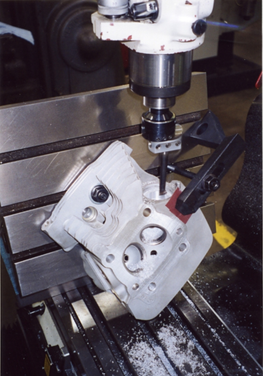
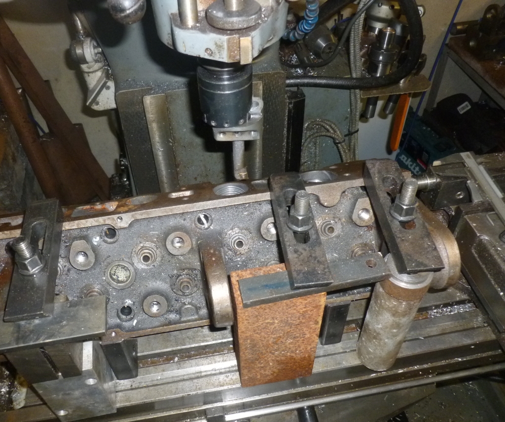
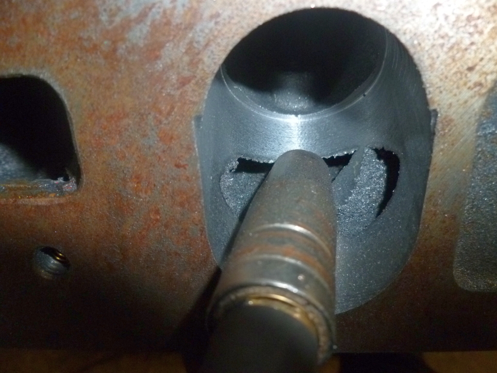
Curiosity got the better of me today..
Used a 50mm boring head with a 12mm indexable carbide boring bar, with a 61.5mm reach past the bottom of the boring head which was just enough to clear the head surface at the full cutting depth
Clamped the head to the milling table, I set the angle of the head just quickly by eye, the first cut was not steep enough so I tilted the head over a little more, it ended up almost exactly 60* from table to head gasket surface
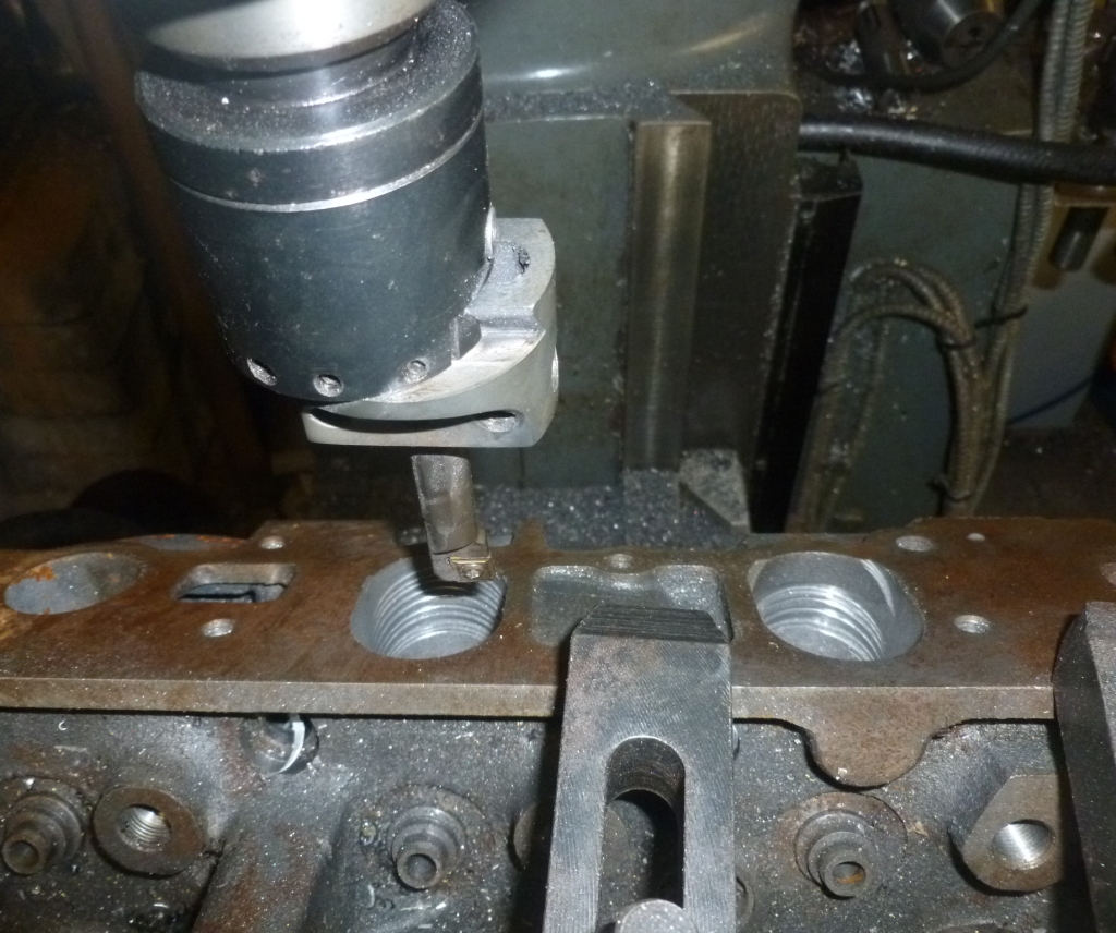
Set the boring head to 38mm, line up with the original port and start cutting the top of the port away in 1mm bites at a time on the Y axis with the X axis locked in place, using the quill to manually "drill" the port and the max depth for the last cut set on the quill travel, 800rpm and it machines the cast very easy with each "bite" feeding the quill down slowly until the cutter just marks the bottom of the original inlet port, then feed in another 1mm on Y axis and feed down until the cutter touches the bottom of the inlet port again and so forth until there is 11mm left between the rocker cover gasket surface and the top of the new port
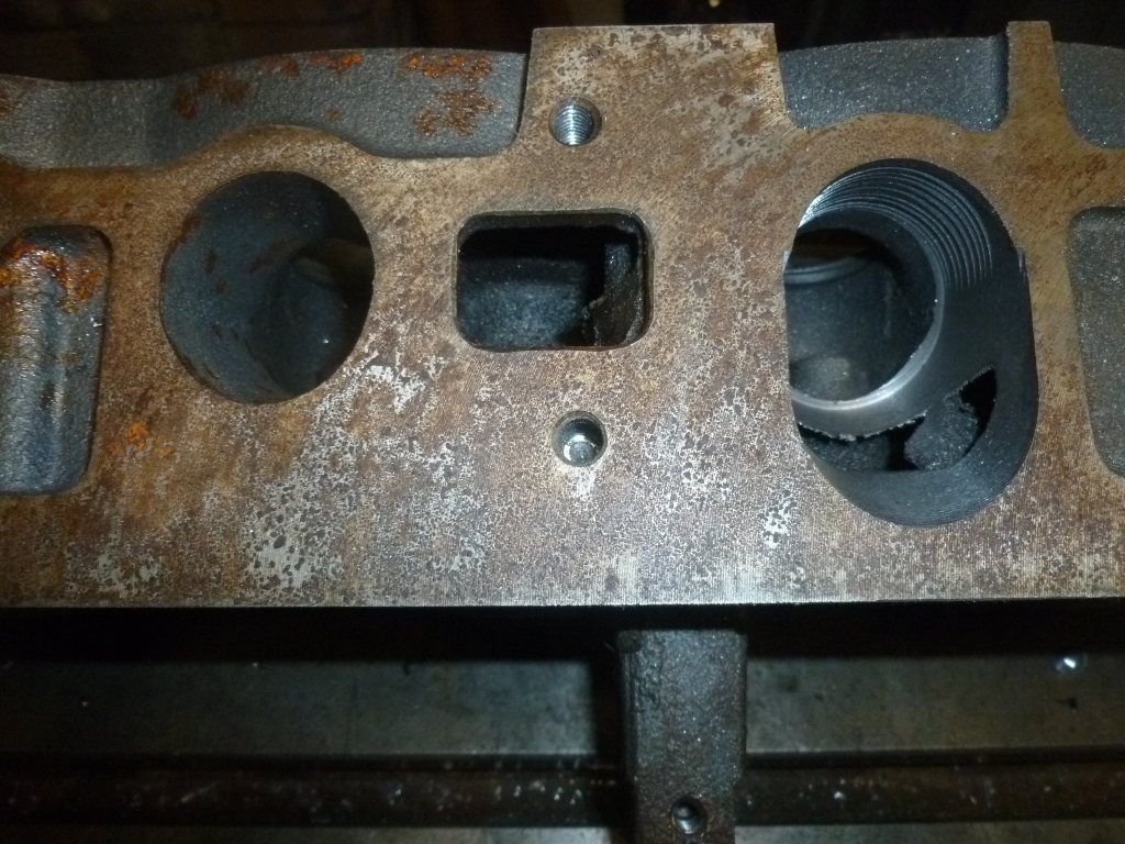
As you can see the top of the port breaks through, but it is quite easy to access, there is a great possibility of welding in a new port roof wig a good mig welder and royal 44-30 mig wire for welding cast iron, stick welding cast is not advisable but this mig wire may do the trick as it flows quite well and tends to stretch rather than snap
A few pics:
Sorry for hijacking your thread lol, at least it's all related anyway : )
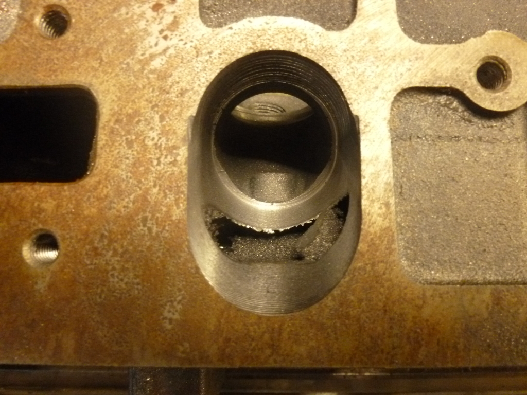
Boring the floor of the port also 38mm at the same angle as the port floor and then placing a raised alloy floor in there would be fairly easy, the main thing would be getting a perfect seal on the port roof, after that it is bringing up the port floor and getting a nice short turn radius, a flat wide short turn
I dare say the injection head would be best suited to this since the roof of the port net to the valve guide is bound to be higher in the port than with carb heads, that is the challenge when boring the port roof, getting the port high enough to give a nice short turn radius with a 38mm port, but it can be done, around 60* to 62* appears to work well, for the boring angle, could get more specific if I get my hands on a scrap injection head
Last edited by RWD fords rule; 19-01-2014 at 16:44.
"Horsepower sells cars, torque wins races" - Enzo Ferrari
Good work Jason. Glad I've got you enthused!
And your angle and dimensions are almost EXACTLY what I have. My new port goes in at 59 degrees and the top of the bored hole was 11mm from the top face (now 12 mm-ish with tube inserted). I reckon we can go a bit higher -say 8mm and have an even steeper port entry. It would break though into the camshaft chamber, but is easily sealed either with epoxy or weld.
Presumably you would just weld in a half-pipe to seal the new port roof and make an alloy stuffer for the new port floor? I didn't personally want to go to the bother of trying to weld cast-iron. I'm not a bad welder, but have never tried it before and was worried about f***ing everything up!
I can see how your method has advantages over mine; you could have a nice mega-flowing D shaped port. And many people do worry about the longevity of epoxy (needlessly I reckon). I think when they see your new downdraught head, there will be a queue at your door of punters wanting a replica!
Lol yes you got me looking into this, good to know the angles are very similar, yes the roof is quite close to breaking into the cam area on the pair of middle cylinders but as you said this would be easy to weld before boring, a friend has a damaged injection head I will have a go at boring welding and flow testing, should flow a hell of a lot more air than any hand ported or cnc head, without any shadow of a doubt, especially with a nice short turn radius and shape, the throat can still be made much larger and wider as usual to help air flow around the turn and past valve
"Horsepower sells cars, torque wins races" - Enzo Ferrari
Yes, weld in a piece of light wall steel pipe would be the plan, will see how it goes and then an alloy stuffer with a really nice shape
If everything worked out well there would be one hell of an advantage vs other engines in 2.1 8V classes, I dare say a night and day difference : )
Did you get your up and running yet? will go very well I am sure
"Horsepower sells cars, torque wins races" - Enzo Ferrari
I'm a way off getting it all together and running yet. Whilst the engine is out of the car, I intend replacing the Type 9 gearbox with a close ratio Quaife or Tran x 4 speed. Past experience with hillclimbs and sprints has told me that I will never need more than 4 gears ( usually no more than 3) and there is an 11kg weight saving by going to the 4speed. I'm trying to compensate for the increased weight of the pinto over xflows and more modern engines by shedding weight wherever possible.
I dare say you' ll have a downdraught Pinto up and running somewhere before I do. I tinker like this as a hobby really, and then only when I have some spare time. But the old Pintosaurus is not yet extinct! 16 valves? Who needs 'em!
Great read this, keep us updated
I got my bits and bobs back from the machinist a couple of days ago.
Block bored to 90mm;
http://s1286.photobucket.com/user/me...tml?sort=3&o=4
A few shots of the head. I had it skimmed 1.5mm; new K-Liners; new cam bearings; 3 angle seats etc.
http://s1286.photobucket.com/user/me...tml?sort=3&o=9
http://s1286.photobucket.com/user/me...tml?sort=3&o=6
http://s1286.photobucket.com/user/me...tml?sort=3&o=2
I trial fitted an inlet valve to check for valve spring fitted length. Blow me down- exactly 37mm which is correct for the Kent springs. You don't need a flow bench to tell that port will flow a shit load of air. Just look down the port!
http://s1286.photobucket.com/user/me...ml?sort=3&o=11
The crank just needed a light polish as it was in really good condition and had previously been ground to -0.25mm;
http://s1286.photobucket.com/user/me...ml?sort=3&o=10
After much head scratching, I decided to go for a good 8.5" clutch which will bolt to this nice steel flywheel - 2.9kgs including the integral ringgear! OK I know a 7.25" clutch has less reciprocating mass, but this project has already cost me a lot of money so I went for a less expensive option. I will be going for one of those Retroford 5 paddle clutches. The guy (Dave?) assured me it will be fine at 8500rpm as he has one on his duratec engine which regularly sees 8500 and has never had a problem. Good enough for me.
http://s1286.photobucket.com/user/me...tml?sort=3&o=0
This is the old 2.0 litre short engine (head has been sold to try and claw back some cash!). I took off the brand new Luk clutch and was surprised to find an alloy flywheel!
http://s1286.photobucket.com/user/me...tml?sort=3&o=3
Unfortunately the clutch mounting holes have gone a bit oval and I certainly wouldn't want to re-use it in it's current state. I'm sure it could easily be welded up, machined true and drilled and tapped to get it as good as new, but I can't be arsed
The old short engine is in really good condition if anyone needs one. It's not a 205 block, but the bores are not worn (still see honing marks) and it is at + 1.00mm;
http://s1286.photobucket.com/user/me...tml?sort=3&o=1
I may even leave the alloy sump on (!) as I intend running the 1600 sump with a welded in baffle. Same depth as the alloy one but lighter!
That's all for the moment.
Cheers Chris.
This is the clutch I'm thinking of using;
http://www.retro-ford.co.uk/shop/con...h-kit-bc008pad
Last edited by MemphisTwin; 09-02-2014 at 18:01.
Want to sell the ally flywheel? I might be intrested is there any photos of it too?
Chris I'd be interested in the 2.0 bottom end and sump. I've pmmed you
There's a photo of the alloy flywheel on the old 2 litre bottom end in a previous post, but here it is again;
http://i1286.photobucket.com/albums/...psa077a352.jpg
As I mentioned, the clutch mounting holes in the alloy have gone oval, and because they are so close to the outer edge of the flywheel, they are bulging as the alloy has stretched. I wouldn't use it as it is - your cover plate coming off at 7000rpm could seriously ruin your day.You could always drill and tap some more holes, or weld up the current ones and re-drill. Sounds like a lot of work to me.
Or steel Timesert them - cheap fix maybe?
Easy fix for the alloy flywheel would be to drill the m8 holes out to 8mm, then buy some short M8 12.9 grade allen bolts and M8 flanged nyloc nuts, torque then up to spec leaving the nyloc nuts at the back of the flywheel, will work if there is a flat surface at the back of the flywheel, securing the clutch cover much like the steel friction surface in the flywheel
Other option would be to re drill the M8 holes and dowel pin holes at a new position, that would also work however you would still have alloy threads rather than steel, bolts would be the easiest reliable solution imho
"Horsepower sells cars, torque wins races" - Enzo Ferrari
Well the flywheel is done and was turned round in about 10 hours. I don't know if I am going to put it in the spares box or sell it just yet.
Basically I removed the old helicoils welded up the outer edge of the holes skimmed the outside of the flywheel and the redrilled and helicoiled the m8 holes. I then skimmed up the damaged face where the crank bolts had chewed the face and cleaned up the face that the flywheel mounts to the crank on. I then refitted the ring gear after I had blended most of the damage out of the teeth by freezing the flywheel and heating the ring. The final touch then was to scolap out the ring gear and tap it to fit 3 anti rotational grub screws. Obviously it will need to be rebalenced to the relevant bottom end but it is functional and looking good!

Great work John.That looks a lot better !
Thanks for that. A little time and it is mint. Like I say whether or not it goes on the Mrs fairly standard pinto on not is I different matter. I'll hang onto it for now though.
These little beauties arrived the other day.
http://s1286.photobucket.com/user/me...tml?sort=3&o=2
http://s1286.photobucket.com/user/me...tml?sort=3&o=1
http://s1286.photobucket.com/user/me...tml?sort=3&o=0
Keihin semi-downdraught FCR39 Flatslide racing carbs. They will need re-spacing and jetting to suit. Allens Performance are experts in this type of carb and have agreed to re-space them for me to suit the Pinto port spacing of 102mm. I will have a simple manifold fabricated out of alloy tube and a corresponding alloy flange.
More later.
 Posting Permissions
 Reply With Quote
 [/URL]
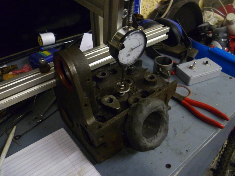


Bookmarks