


Nice work, need don't worry about sealing the trumpets to the fixed runners they slide on, no air will flow in a small sliding gap
How much adjustment are you getting there looks good

Nice work, need don't worry about sealing the trumpets to the fixed runners they slide on, no air will flow in a small sliding gap
How much adjustment are you getting there looks good
Last edited by RWD fords rule; 18-03-2014 at 12:43.
"Horsepower sells cars, torque wins races" - Enzo Ferrari
Hi jason..its got 90mm slide adjustment...plus i can make the top bellmouth longer if required...i put the seal on because i was worried about the top injectors and fuel escaping.......it would be nice if i didnt need them...but im not sure...there is no info available (that i can find) and i wont no untill i test...
what do you think...mark
i had a set of 1980's ex mountune btcc adjustable inlet trumpet throttle body set up for a bmw engine, it was very similar to yours, the only real differences were that it slide on only two but bigger longer liner bearings, and like jason said didnt have seals between the fixed and moving trumpet sections
Thanks graham..did it have the top injectors...if i didnt have the top injectors then i wouldnt worry....but im worried about fuel seapage from the top injectors....i really dont want to use the seal....mark
About the seal, I imagine you will only be using the outer injectors at mid to high rpm when the trumpets will be in the short position, in the short position you should have a good "seal" between the outer and inner parts of the trumpet, if you use a small clearance it should be fine, I would not worry about it, you could always fit some seals later if needed but I reckon you won't need them since at high rpm you will have at least a 90mm long overlap
"Horsepower sells cars, torque wins races" - Enzo Ferrari
Thanks guys...i think your right....yes jason thats right mid to high should be short so a 90mm over lap....as you say i can always add afterwards....
Cheers mark
How are you planning to move the trumpets? you mentioned a cam mechanism, is it going to be a one step operation from long to short?
Was looking at R1 variable length inlet "YCCI" to give increased low o mid range torque, they use a set of large fixed trumpets for high rpm and then have a second set of trumpets that sit on top of the fixed trumpets at low to mid revs, then the upper trumpets separate moving upwards away to create a gap between the two trumpets in order to alter the pressure wave length/timing, looks like they use a motor to move the upper trumpets
It must be able to move super fast
"Horsepower sells cars, torque wins races" - Enzo Ferrari
Yea its controlled by the ecu so in theory yes any point...but in practice probley just long and short at least to start ...thr linear actuator im using is 20mm second x by my cam ratio...
I looked at doing a 2 stage trumpet but i couldnt find an easy way to incorporate the top injectors..(when its short and i want the top injectors the top stack moves up so would the top injectors...or i looked at some top stacks that swivled out the way but same problem with top injectors in the way... theirs a nice ducati sliderstack with cool levers but for four rams i would need 2 driven moters and timing together and space are the problem...
At the moment i have only designed a relay system for 3 off points ...so any three height points triggered by the associated rpm/throttle position on off at a speed of 20mm a second x my cam ratio......should in principle give me pertty much full controll of position movement....i hope...
The reason why ive made the structure rigid and tied in to the head is the amount of force and speed of the actuator.....the hope is it will keep working for at leaste a full race....
Mark
Super thread, your way of sealing the tubes is interesting idea. We used press fit cast iron sleeves, they sealed well for almost a season and then started leaking. Tried a can of Locktite head sealer which help for a few races until an inlet valve let go destroying the head.
You have just taken the idea to the next level.
BTW - are u using a custom length conrod ?
We ran a set Wiseco Honda TRX 450 (2004-5) pistons with Hyundai rods and if memory serves me correctly they where that length
Hi darth..funny it was your post ages ago that got me thinking about downdrafting the head...yes very similar idea im using 2.0 xe rods with a 20mm pin for hussy 92.02mm pistons 23mm ch height..rod length 144mm and stroke of 80mm(might go 93mm pistons )
Mark
Shit sorry I got u into this project then
...call it inspiration...
I'll be posting up pics soon of a new d/d head the guys are busy with. Plan is to bolt on a Hillborn injection system this time.
Please DO!Originally Posted by DarthVader
"Horsepower sells cars, torque wins races" - Enzo Ferrari
As jason ....pics required...good for new ideas
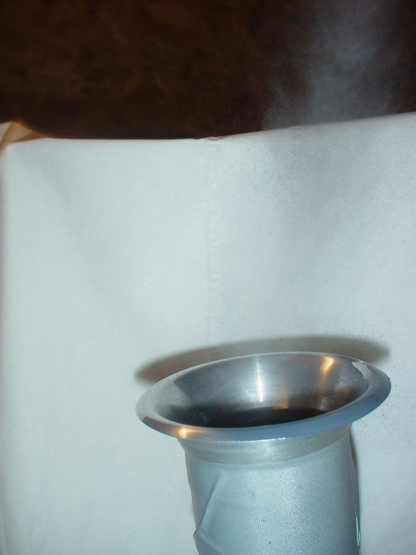
Ok been doing some science......
I needed to see if i needed a seal in the base of my sliding velocity stack...i believe that i dont as posted above...but thought id have a look any way..
So
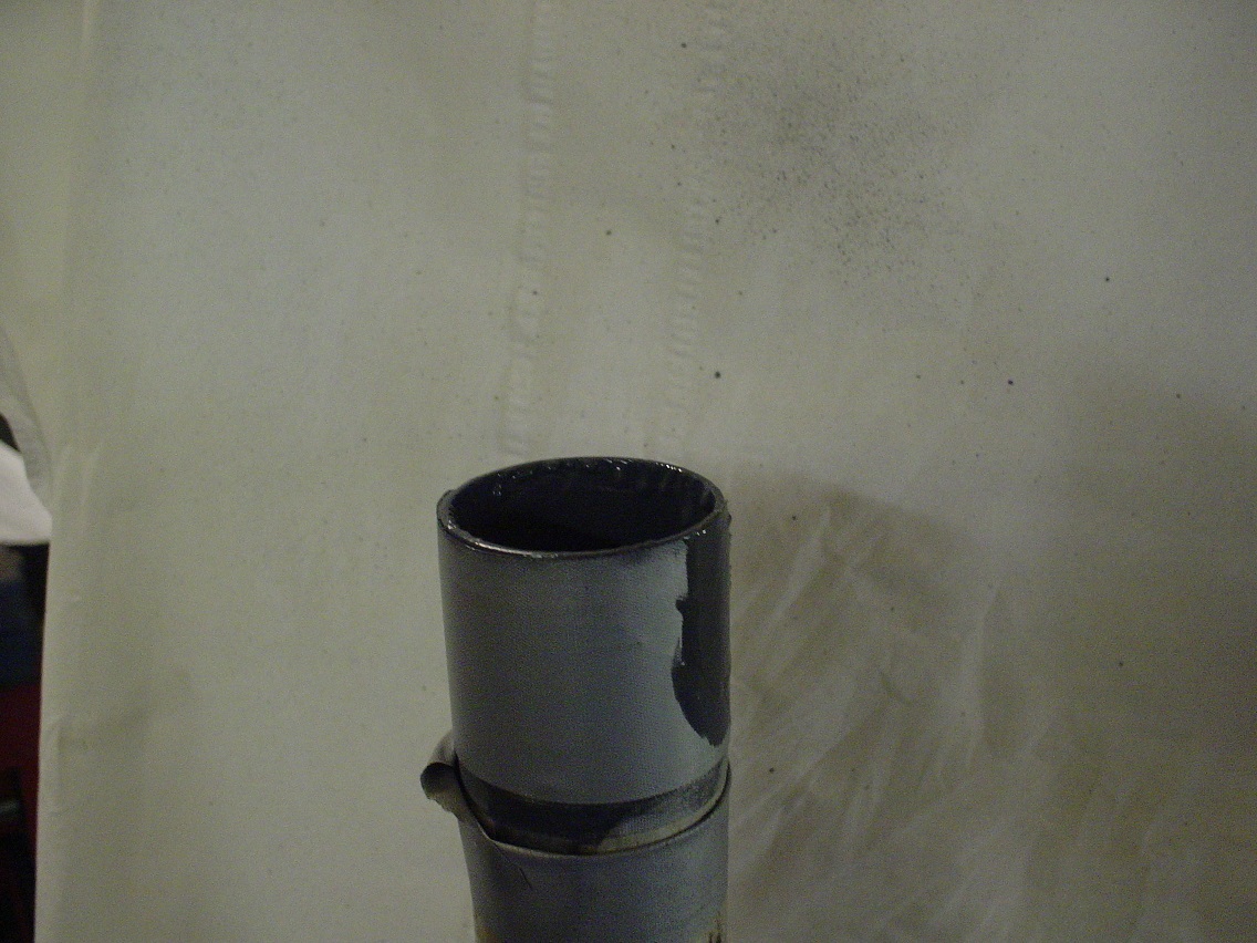
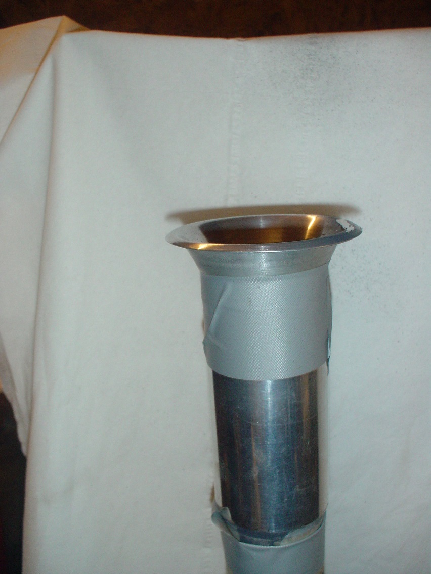
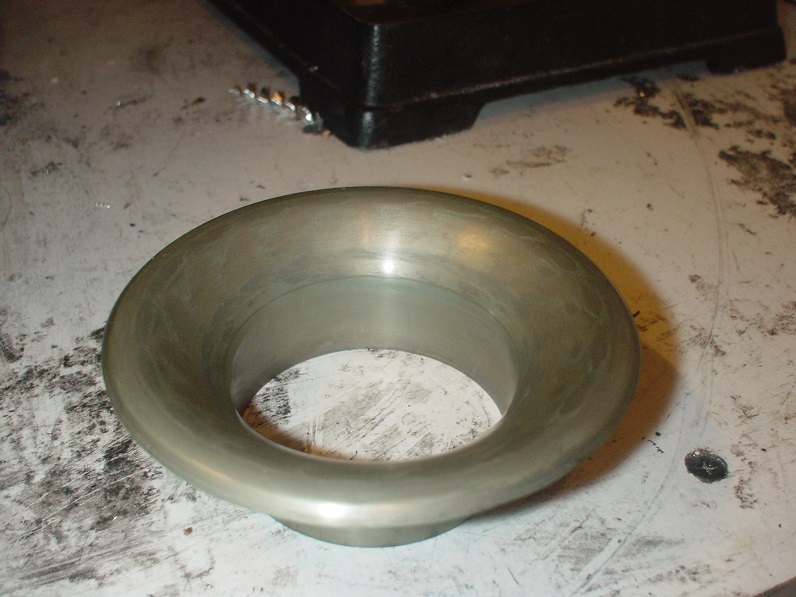
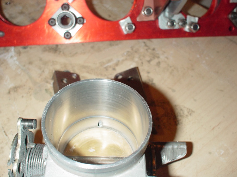
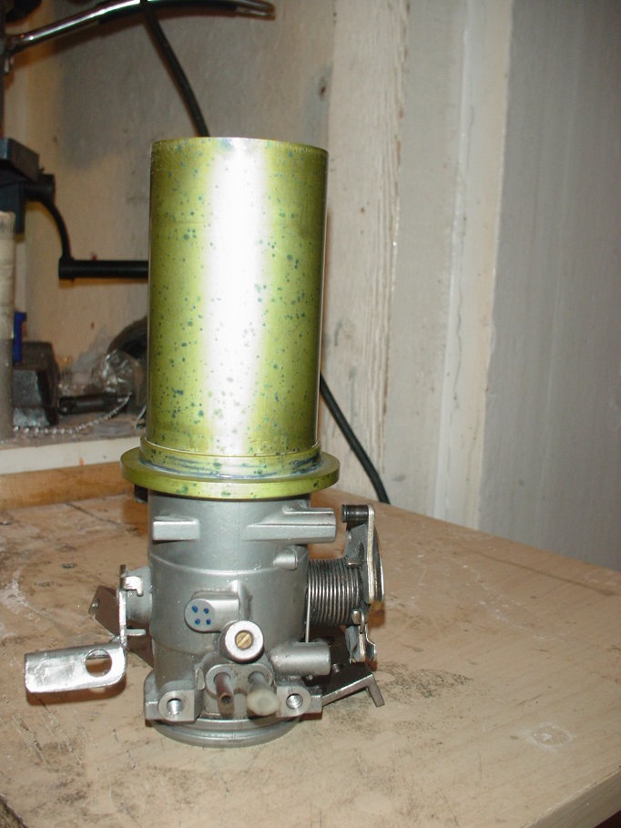
made a quick sliding velocity stack and taped on the bell mouth i made...connected it up to my vacume cleaner (vaxwet and dry)
and marked fully open fully closed...
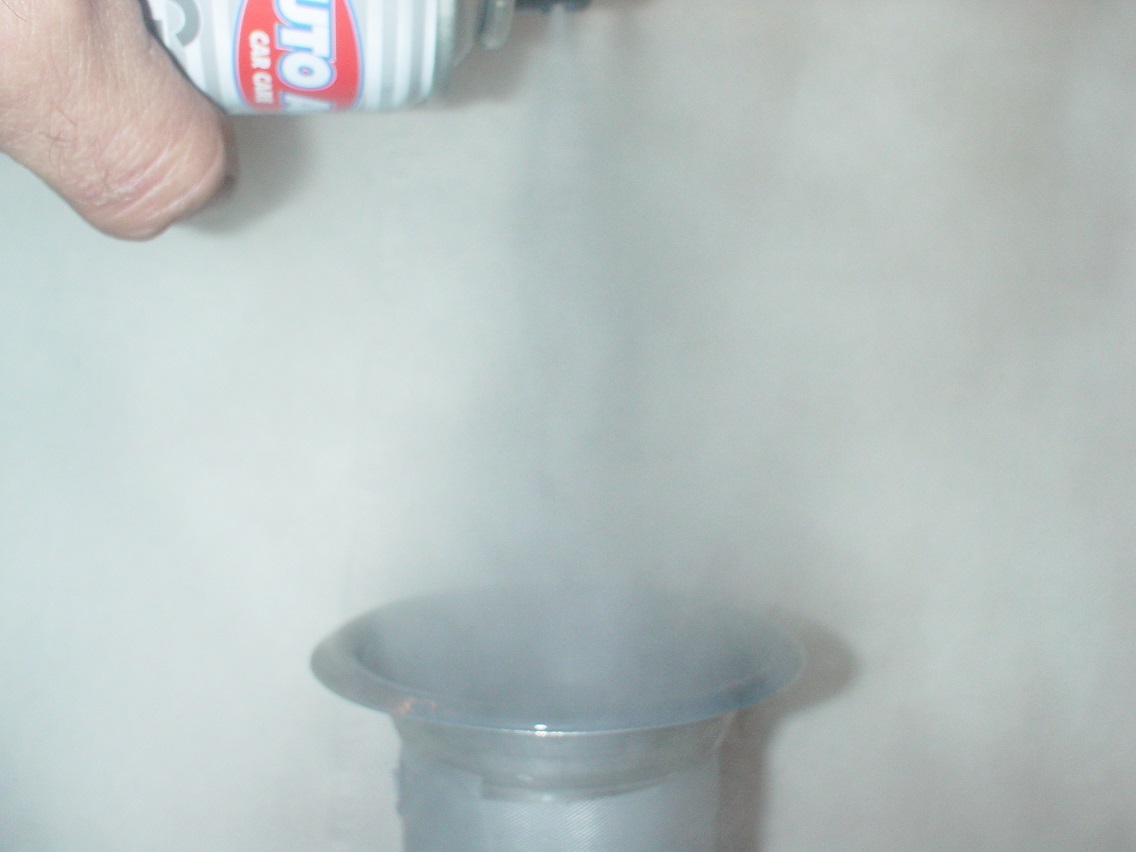
Then to simulate the injector i held a can of spray over the inlet...
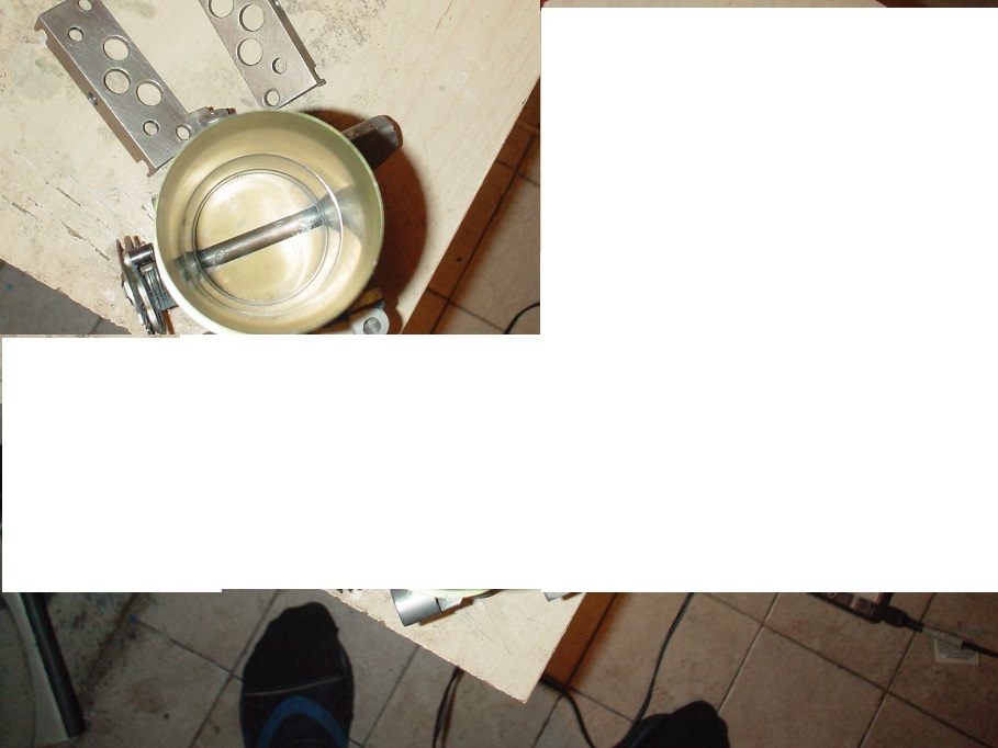
tried it from the right in fully open and fully closed (you can just see the spray if you look close
tried it high just of centre (you can see the spray if you look close)
I can def say that you dont need the seal if the injectors are working in tandem with the engine..
just for science i tried many different angles of spray attack...and you can see the bell mouth working even if you spray at 90' to it..
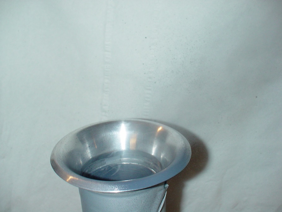
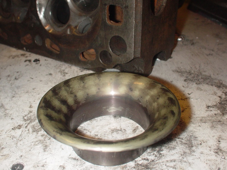
for a comparison i sprayed after the vacume was turned of and i got massive leakage on the side the spray hits..( you can see the paint on the right hand upper side)
Something else also became apparent whilst doing this...i will have to fit some sort of slider seal to stop any crap from picking up and seizing the movement..
( i guese thats why rams ect have slider seals.... makes sense)
Mark
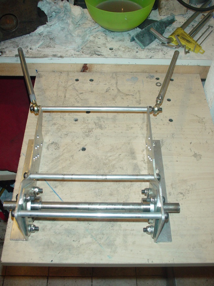
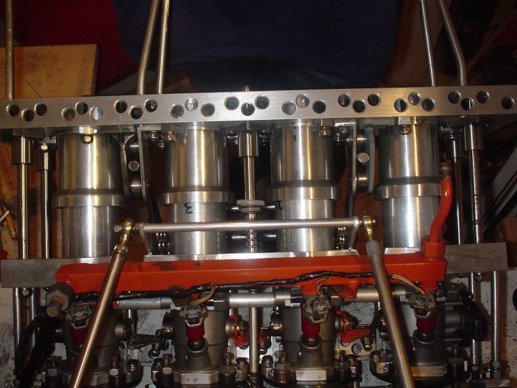
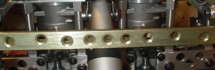
Ok made all the adjustable clamp screws..this makes it easy to set the tensions to get everything parallel and locks all the parts together...
next started to make the lifting cams...
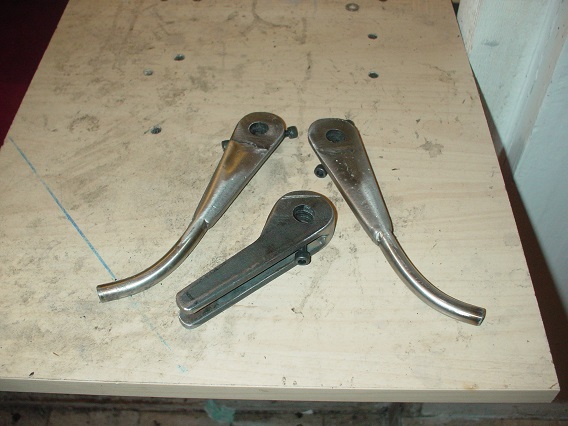
Most of the bike adjustable rams are two stage and the lift is about 40-50mm .so couldnt use that design
next looked at the f1 version
this is close..but again only about 50mm movement....to move 80mm i will have to move the upper injectors as well as the stacks..
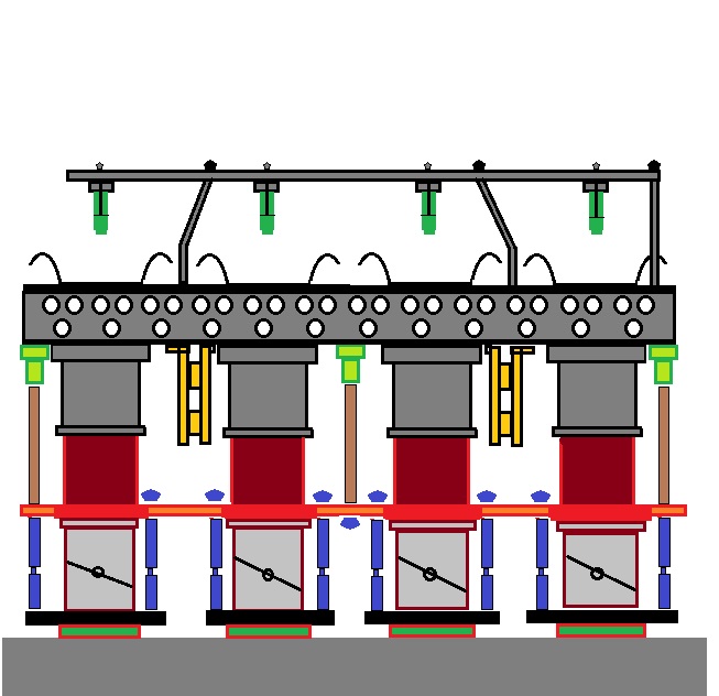
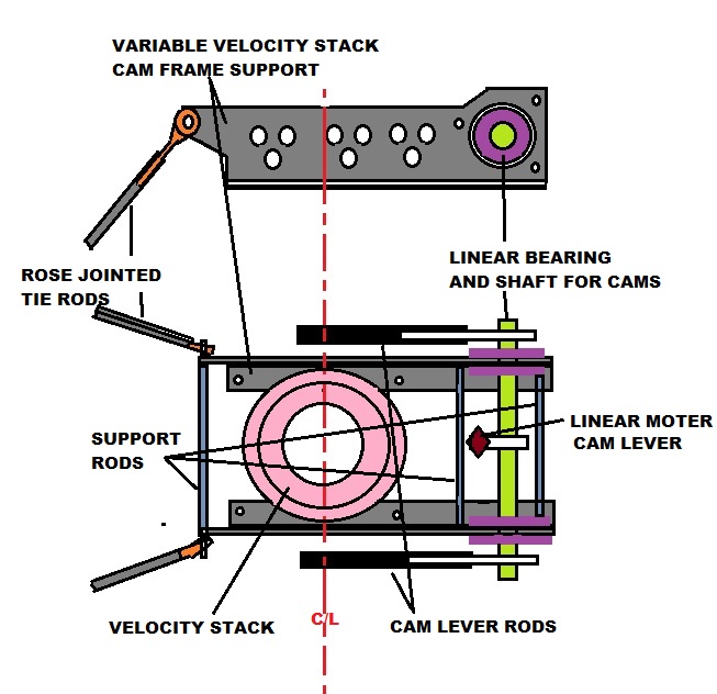
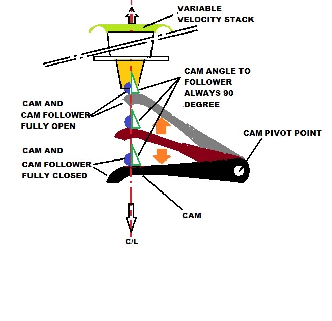
so reversed the design above and keeping it strong and simple used the space i had..
this is the kind of idea
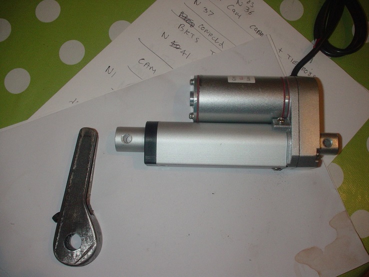
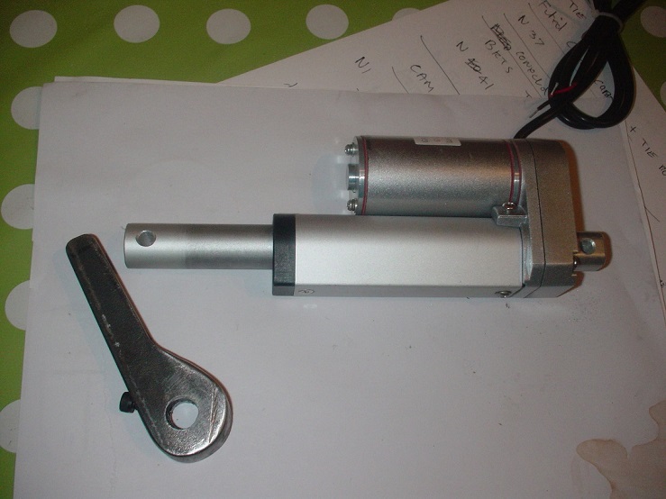
the lever cam bearing housing and the lever cams ive built them strong but light..the actuator has a force of 28kg and 30mm a second no load and 20mm a second load
ive used a lever type fulcrum to increase the speed so my minimum is now 35mm a second load and max 50mm a second load....so needs to be strong..
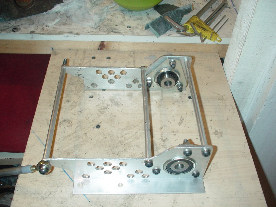
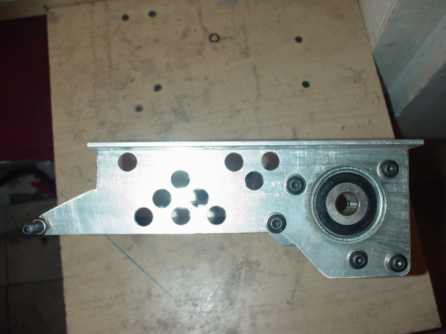
the housing design
finished
and with the bearing shaft in place..
the lever cam arms..these need to apply the upward/downward pressure at 90 degrees to the movement so needed to work out the actual cam profile and then transfer to the lever end..
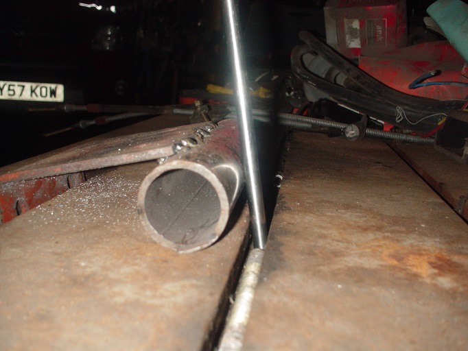
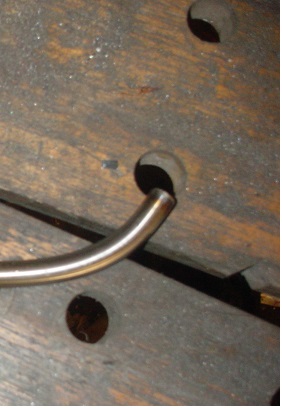
used 10mm tool steel for the cam profile welded to steel supports
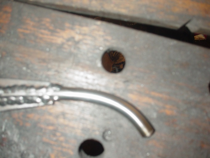
made a jig and bent the initial profile..x2 off
then cut
and position welded before flood welding
flood welded and the center driven lever made..
ive put lock screws to position the levers before they get welded..then all the welded areas will have to be painted..
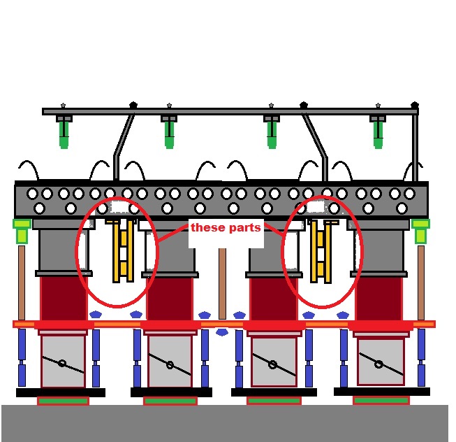
next the bearing cam followers that connect to the top plate...
the parts circled in red
mark
Wow....
Stunning work mate...
You call this a hobby?!
I would say you're a pro or, at least, more capable than the average amateur.
Guys like you, Graham and a few more I've seen here, given the chance to be put together, WOULD give a lot of headaches to many big companies out there.
The work guys like you can do with your hands is nothing less than amazing and a big inspiritation for guys like me, who can appreciate it and, the fact that you share it here... thanks.
Cheers and keep up the good work,
Mário Santos.
Thanks guys....i do it to unwind...and have fun..i work 6 days a week 9 am till 8pm and on my day of ..its all cars....
Last edited by madragon199; 02-04-2014 at 21:22.
I'm lovin it, keep it up mate
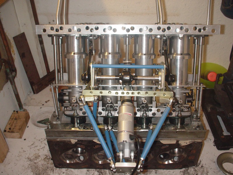
Been busy designing and making parts ....
made the tie rods using thin wall stainless with m6 nuts welded to ends and rose joints fitted to one end..
fitted the cam carrier...will provide some cross rigidity...and fitted the tie rods..
connected the lever cams to the shaft...ready for positioning..will be welded in position when set..
Removed all bkts from cam cover then added to more tie bkts cleaned and painted..connected the tie rods..
started making the cam roller followers as circled in red in above post...
cam follers assembled with sealed bearings and fitted to the top sliding section(2 off).....linear bearings modded and fitted (6off in total)
the holes for the upper sliding stacks drilled as well...
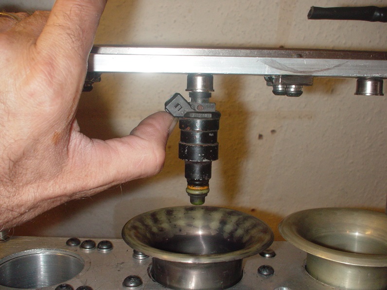
used a cosworth injector rail for the top 4 injectors all modded and fitted ...the ally rails will be used to secure the injectors (when i get some)
injector rail supports made and fitted ....ive designed the height so the injector nozzle will be 25mm from the end of the bell mouth
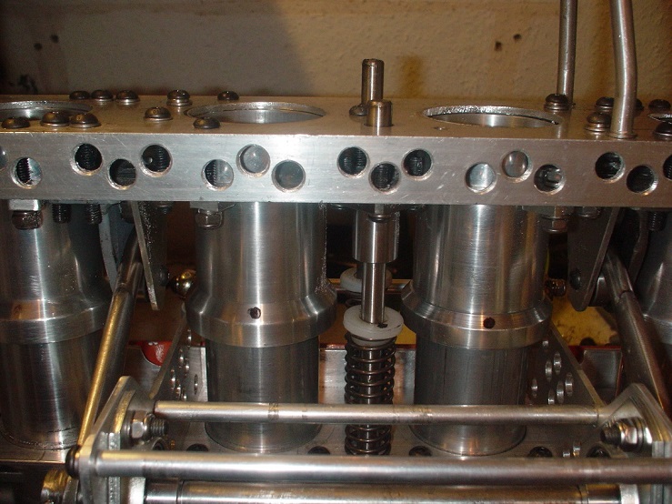
test fitted the top slider to the lower fixed shafts ready for the top sliding stacks..... in the closed position..
and now in an open position...
and when i let go it slides down on its own
Mark
Any updates on this?
I do love a home brewed technical thread trouble is the pics cant come quick enough !
will update tonight ..been on holiday....mark
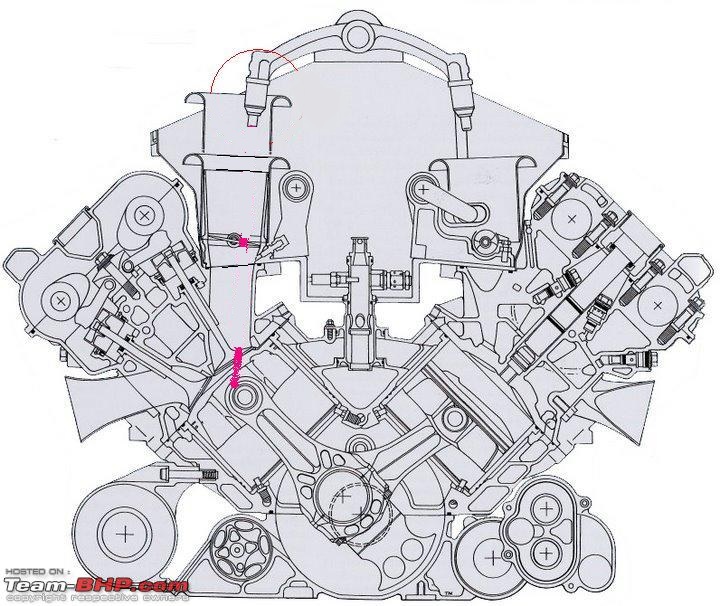
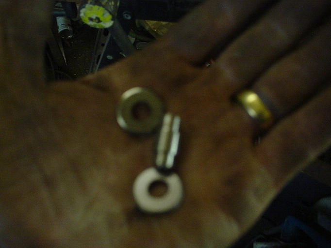
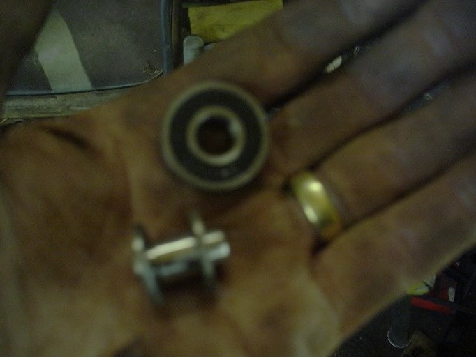
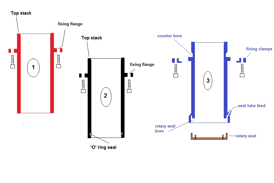
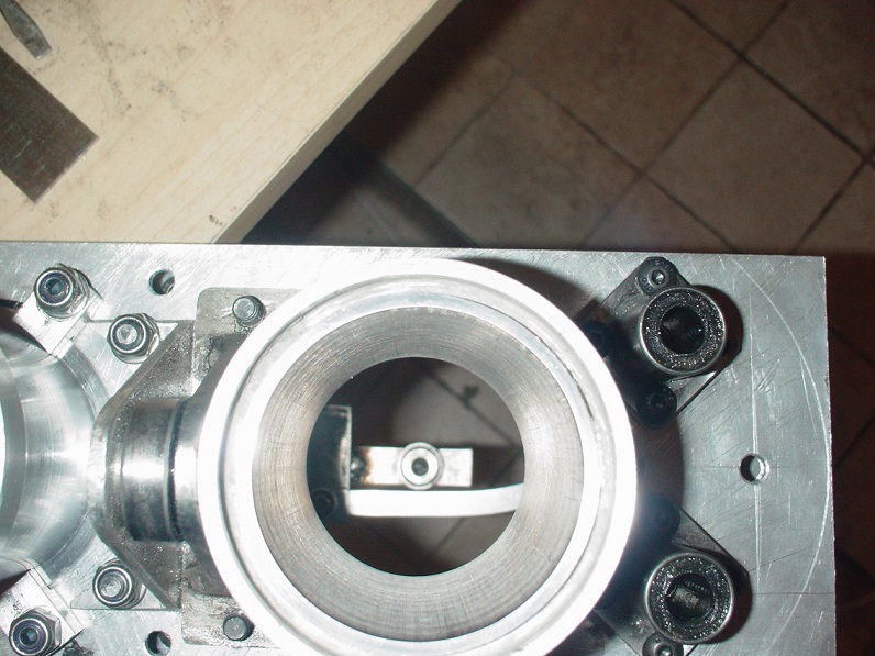
update....Ran some tests with original upper stack (1) in diag ....but as i thought it picked up and started to score the stacks..
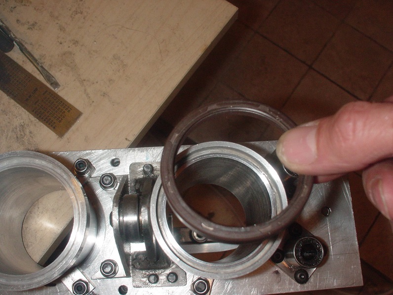
so tried using an o ring as (2) in diag this worked kind of..but only sometimes would jam and sieze up...so ended up with a new design no(3) i also changed the method of fixing ..i needed a way of adjusting each stack to match its mate part exactly ...so used the clamp idea ...works a treat
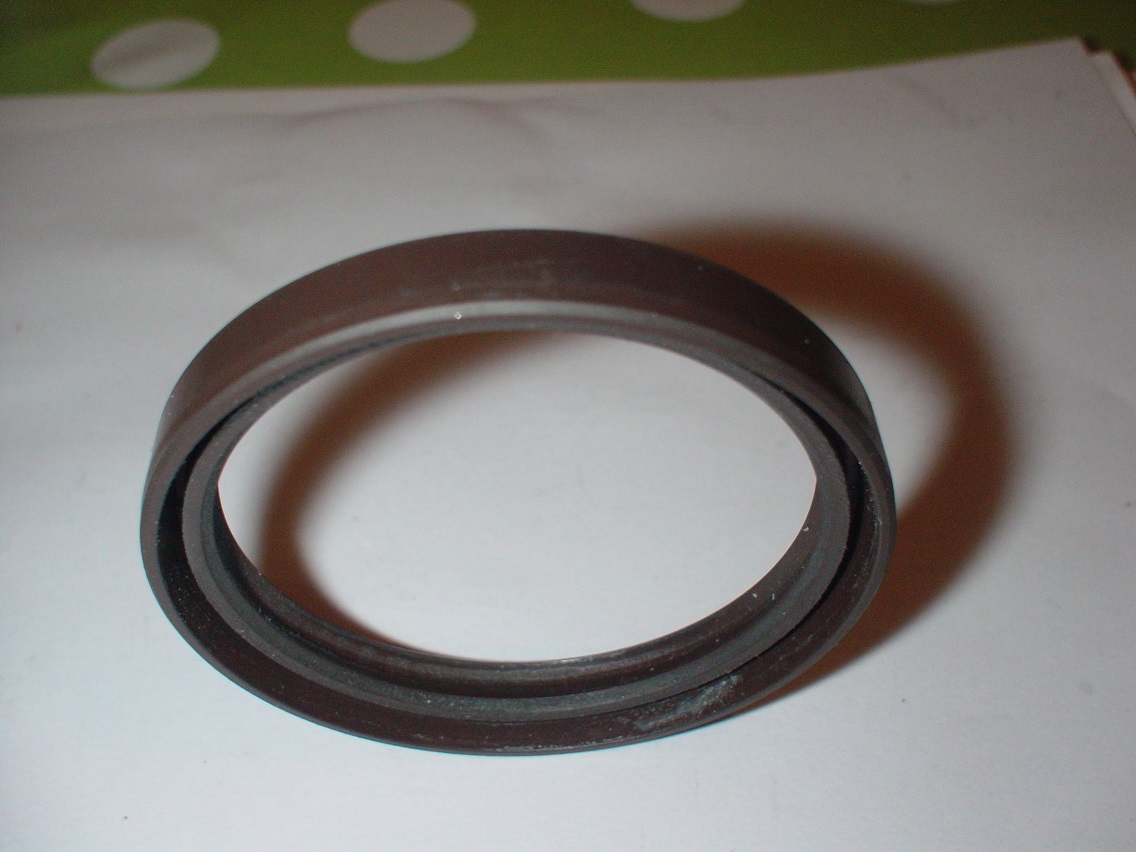
i used a viton rotary seal with the spring removed
......this worked... but it does need lube to run friction free
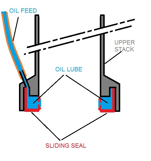
this fits in the counter bore in the top stack...by fixing it upside down and recessing i can create an oiling well that only oils the seal between the upper and lower seals of the seal
this is the idea of the self lube system
a project for later..
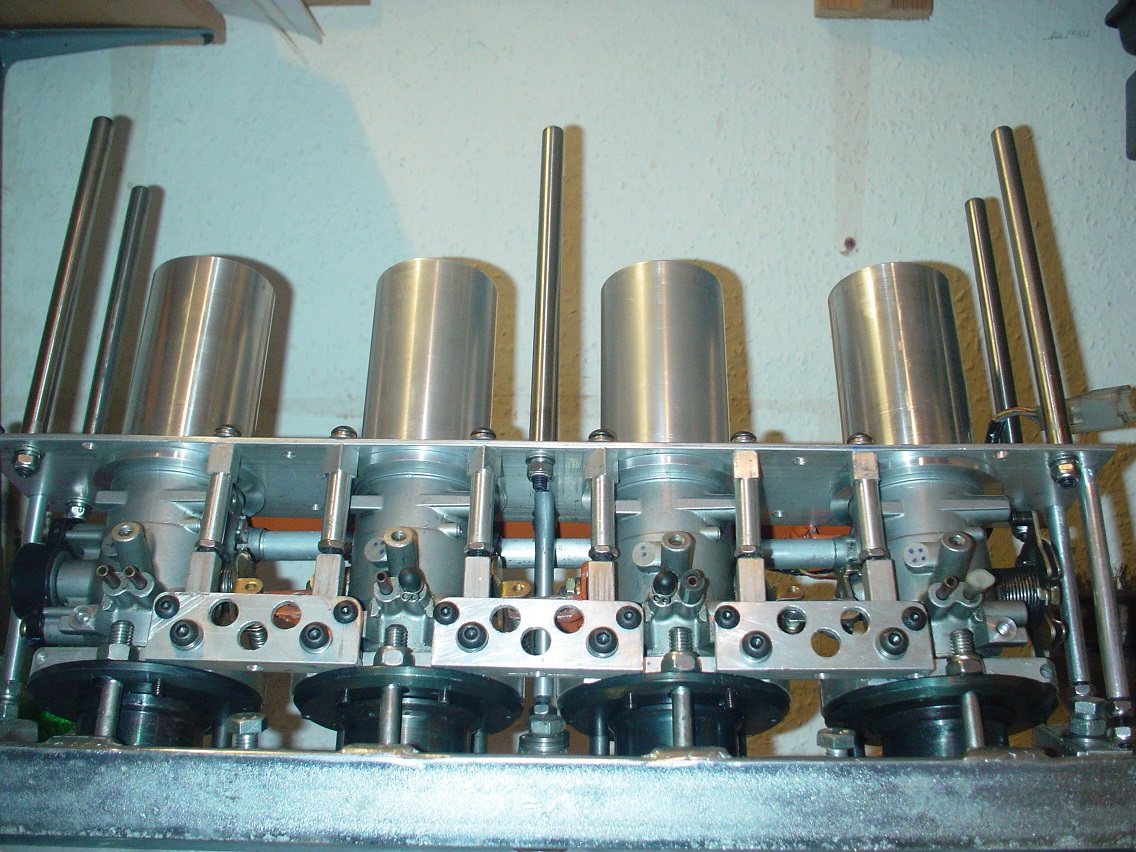
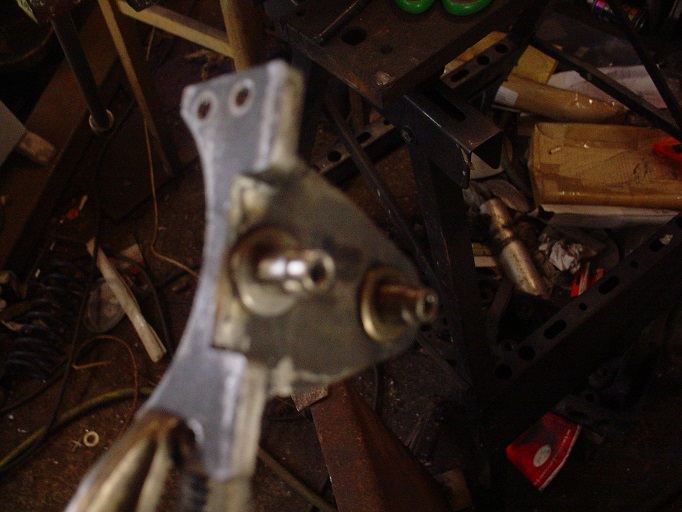
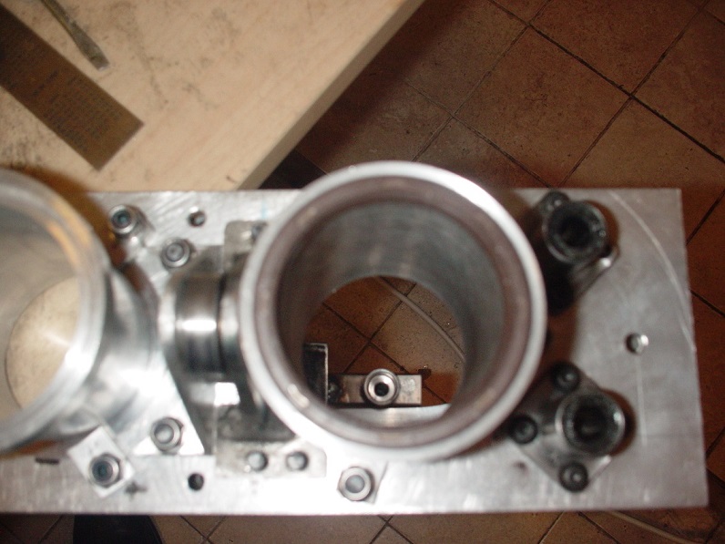
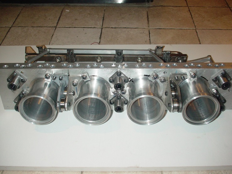
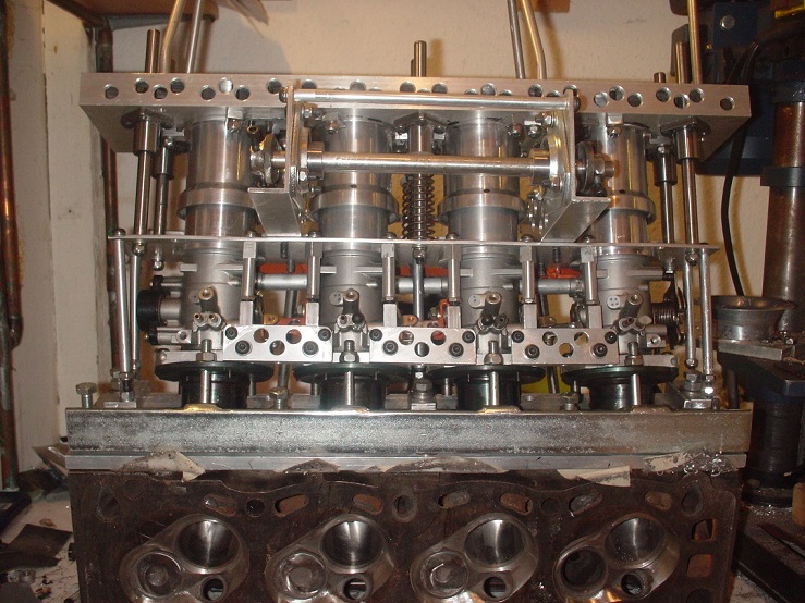
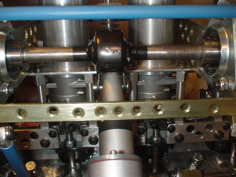
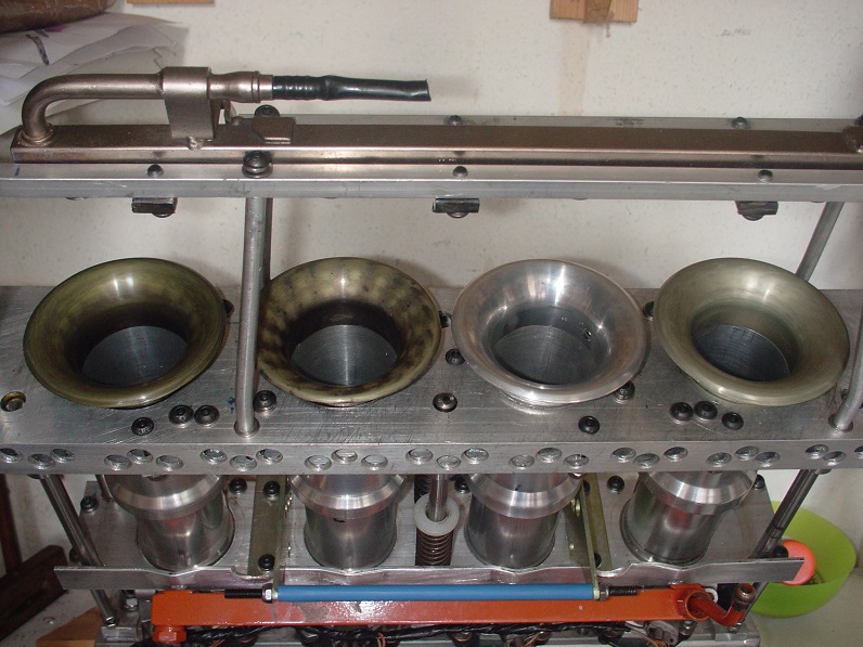
all four top stacks fitted and aligned...
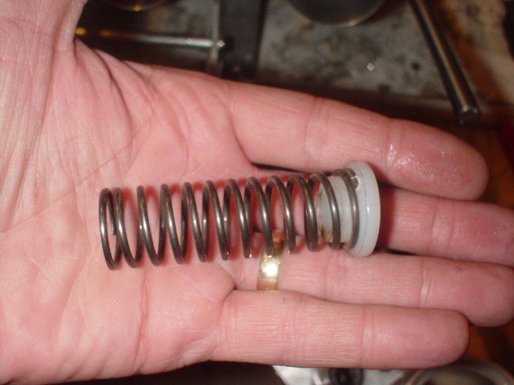
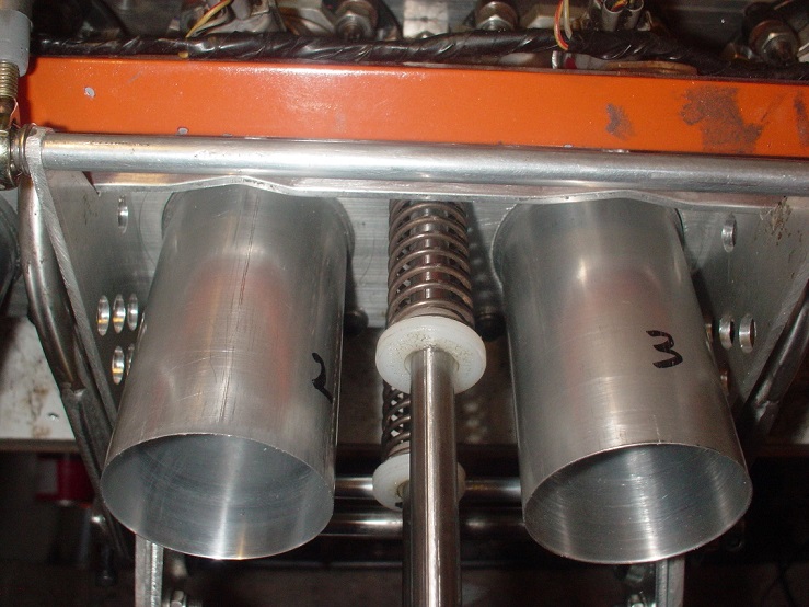
when fitted and trial run i needed a damper at the end of its travel to stop it gently and assist with its release..so made a couple of small shock springs with p.t.f heads..
you only need a pair on the center shafts
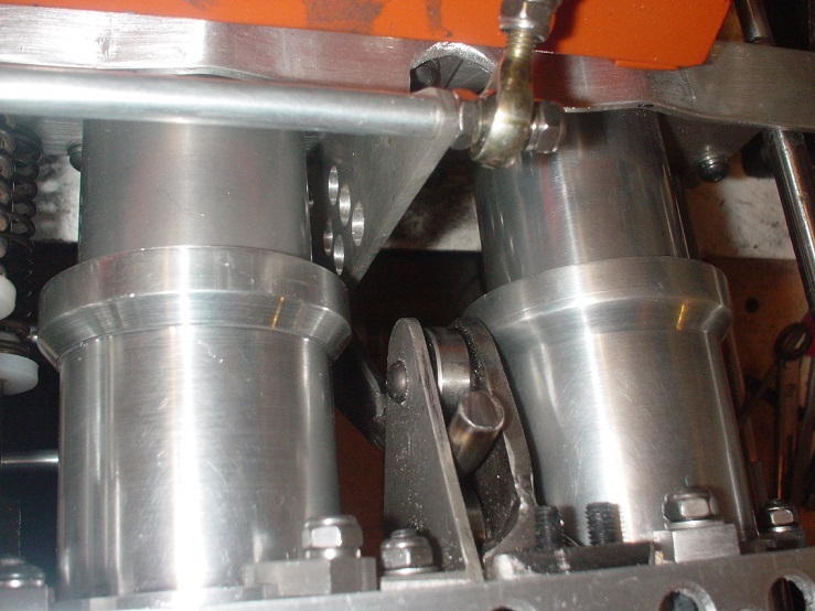
the complete top slider assembled and fitted to the guides( view from underneath)
cam lever and followers and the shock springs top and back
cam close up with follower
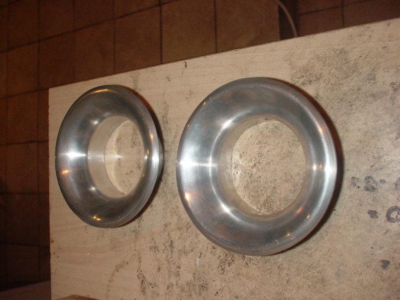
next job is to spin the bell mouths i am going 95mm eliptical shape and fit them on the top side of the sliding stack..the height of the bell mouth is 25mm but obviously i could make them longer if testing needs more overall length ...a pic with the smaller bell mouth to show the idea
the linear actuator i am using 50mm stroke...and the lever arm...need to fix the two together...and support the actuator..(jobs still to do) but getting there slowly
mark
Am absolutely loving this thread
Just read all 3 pages and I am so so impressed. The work and skills are incredible
thanks guys.....cheers mark
i needed to sort out the top 4 injectors ...so i found this injector chart.....basic rule for injector x 4 then divide by 5= total hp. .eg 300cc x 4 =1200 divide by 5 =240hp
injector chart...i found it very usefull...size/part no/type fixing/flow/cars used on.... ect..(not mine borrowed it)
http://awswww.turbosport.co.uk/images/attach/pdf.gif
cheers mark
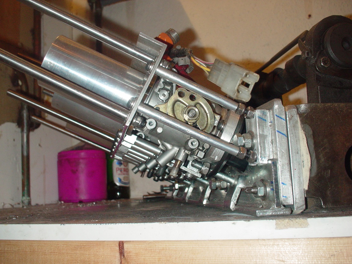
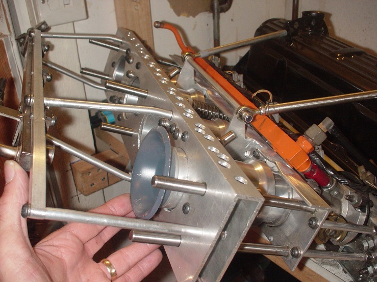
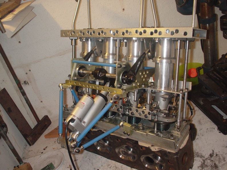
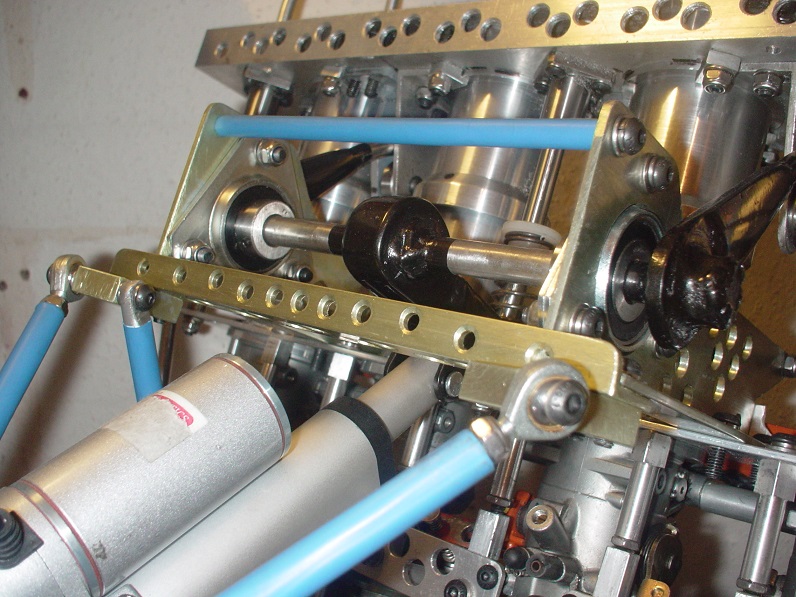
Getting there ...needed to make the support bracket for the actuator(ram) this needs to be positioned down the side of the engine because of space...and needed to be rigid in all directions...i couldn't use a simple bracket because the oil filter and block breather are also in this position so i ended up with a rose jointed double tri pod arrangement...this works really well and gives me adjustment in all axis...used ali drilled and tapped and m6 rose joints ..
with the actuator positioned i could align the cam follower and lever and weld in position...painted the steel parts to stop rusting and assembled the bearings and bkts..
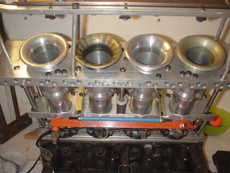
test ran the actuator from the battery works a treat ...80mm travel in 1.6 seconds..or if i use 24v 80mm in 0.8 seconds but i guestimate 1.6 seconds will be fine...pic of the stacks in the fully open position (max travel)
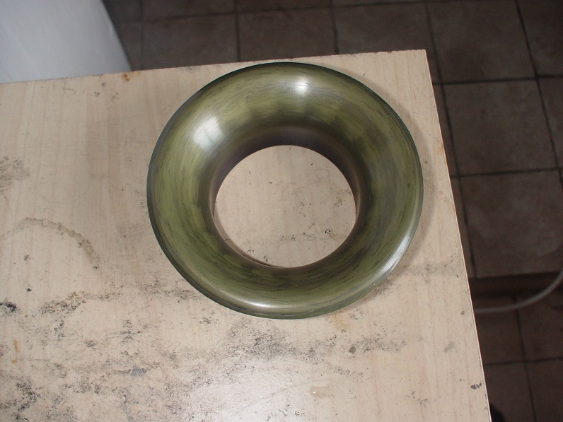
worked out my final bell mouth sizes,,,, a full elliptical bell mouth would end up with a finished bell mouth 127mm..this is to large..i wanted 100mm bell mouth ,,,so 80% full elliptical bell mouths were designed....then spun on the lathe ...
next i need to make the injector fixing bkts...for the top 4 injectors...they will sit here..
but the injectors im using (440cc) havnt arrived yet....
so i thought i would start to protect the aluminium parts...the tri pod tubes i used blue heat shrink sleeving (had a meter left over) works ok and dont look bad...
Then had an idea about color anodising my own parts...
Trip to my 95p store and for under £7 had all the stuff needed...i didnt use any haz chemicles so it was not to dangerous (used the patio table in the garden) the only color the 95p store had was green so thats fine ...pics of the results...very easy to do and no need to muck about..results...
got carried away..i found that different thicknesses and times create different effects..so tiger anodising..
all using the same green just different lengths of time of for each process...
all 4 bell mouths 2 green and 2 still to do....
mark
Awesome stuff. Very impressed with your engineering skills. What car is this going in?
Matt
thanks matt..im squeezing it in a mk 1 escort....
Is the actuator a stepper or straight full stroke out and reverse? How are you planning the control of it to match the engine characteristics? I do wonder how its going to fit in a 'scort though.
"Squeezing" being the operable word.
Great stuff
Matt
its a 12v dc stepper motor..driven from the ecu..using tps and revs for position...so in theory you can set height to match revs....ive tried it in my escort for fit and it doesnt..but it will with a few mods to the escort..at the begging i already measured available space and new i would have to move engine angle and height a bit(within my racing rules) and raise the bonnet (again within my racing rules)..mark
Another bell mouth anodised...went for a darker shade this time...leave longer in both baths..
3 down one to go
i was going to put a how to on this thread ..but i think ill start another thread on easy anodising...
mark
Last edited by madragon199; 13-07-2014 at 19:34.
thanks ....
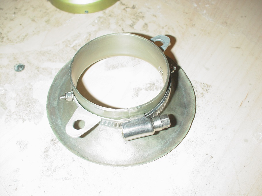
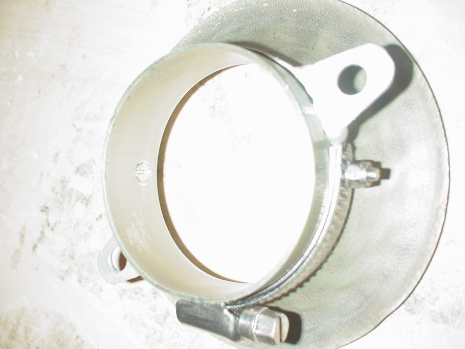
Finished of the fixing for the bell mouths...s/steel jubilee clip with a couple tabs welded on and then fixed with m3 c/sunk screws to stop it coming loose...
its pretty much finished ...but a lot of detailing to do on strip down...
the taper on the inner edge of the throttle bodies needed moving 1 degree to match the overall taper so back on the lathe and a perfect match..
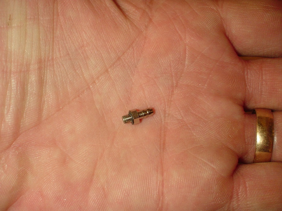
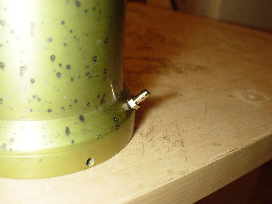
next on the list the auto oiling system for the sliding seals..the first part is a fitting an m3barb at 90 degrees to the taper on the upper body..
The m3 barb
drilled and tapped and locked in position...
you can see ive been mucking about with color anodising the ally parts...most of the parts wont even be seen but there protected now...(more pics on the How to Annodise thread)
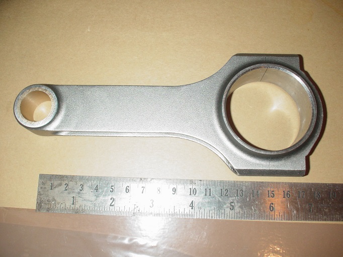
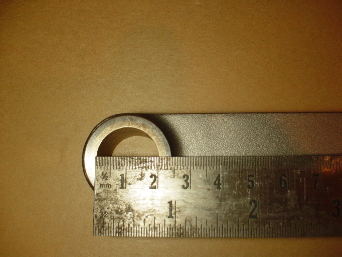
while im waiting for my injectors...
i modified my forged con rods little end to 20mm floating pin....the overall length is 144mm and the big end is a couple mill smaller...the aim is a long rod and an offset crank to increase stroke and use slipper pistons...this is why i needed a 20mm pin to gain the extra mm required
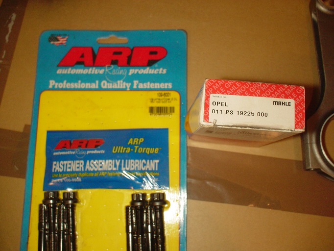
thanks to turbosport member got my arp bolts and big end bearings..
cheers mark
 Posting Permissions
 Reply With Quote


.JPG)
.JPG)
.JPG)
.JPG)
.JPG)
.JPG)
.JPG)
.JPG)
.JPG)
.JPG)
.JPG)


Bookmarks