


Looking good as usual!
Always enjoy updates to this thread.
Shaun

Looking good as usual!
Always enjoy updates to this thread.
Shaun
No Further Movement on this, I am astounded by the skill and workmanship of this set up, Esp for a hairdresser :P
We are all waiting for the latest installment of this thread. It is amazing what can be achieved by using a bit of ingenuity.
Tom
To finish first, you must first finish
busy season at moment working seven days a week..will update tonight..Cheers mark
Can't wait for this!Originally Posted by madragon199

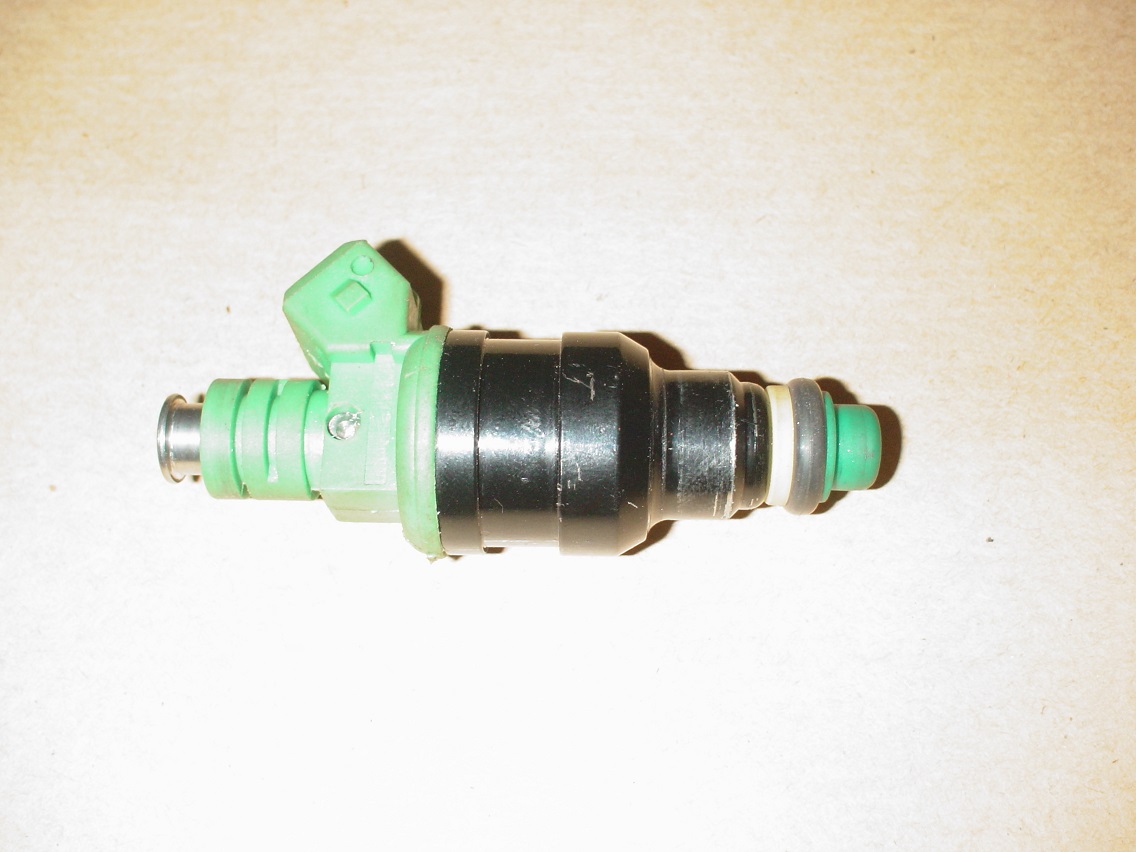
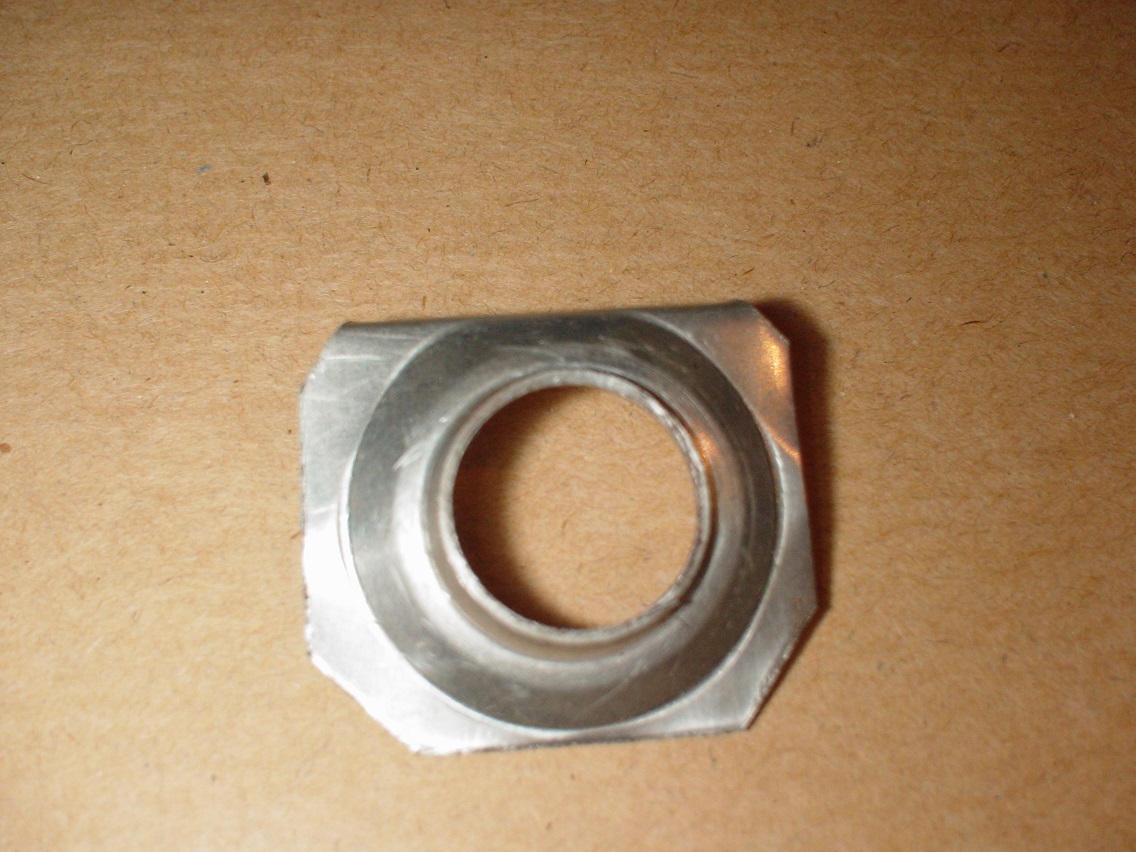
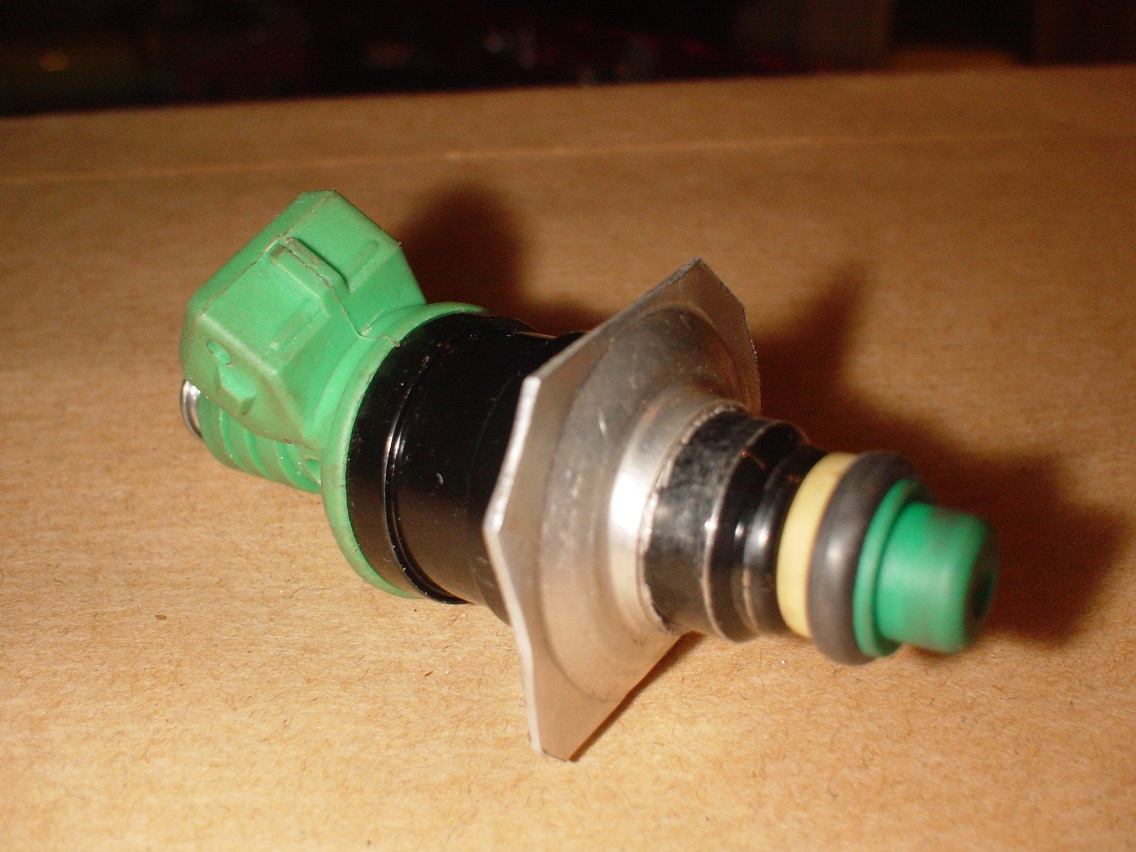
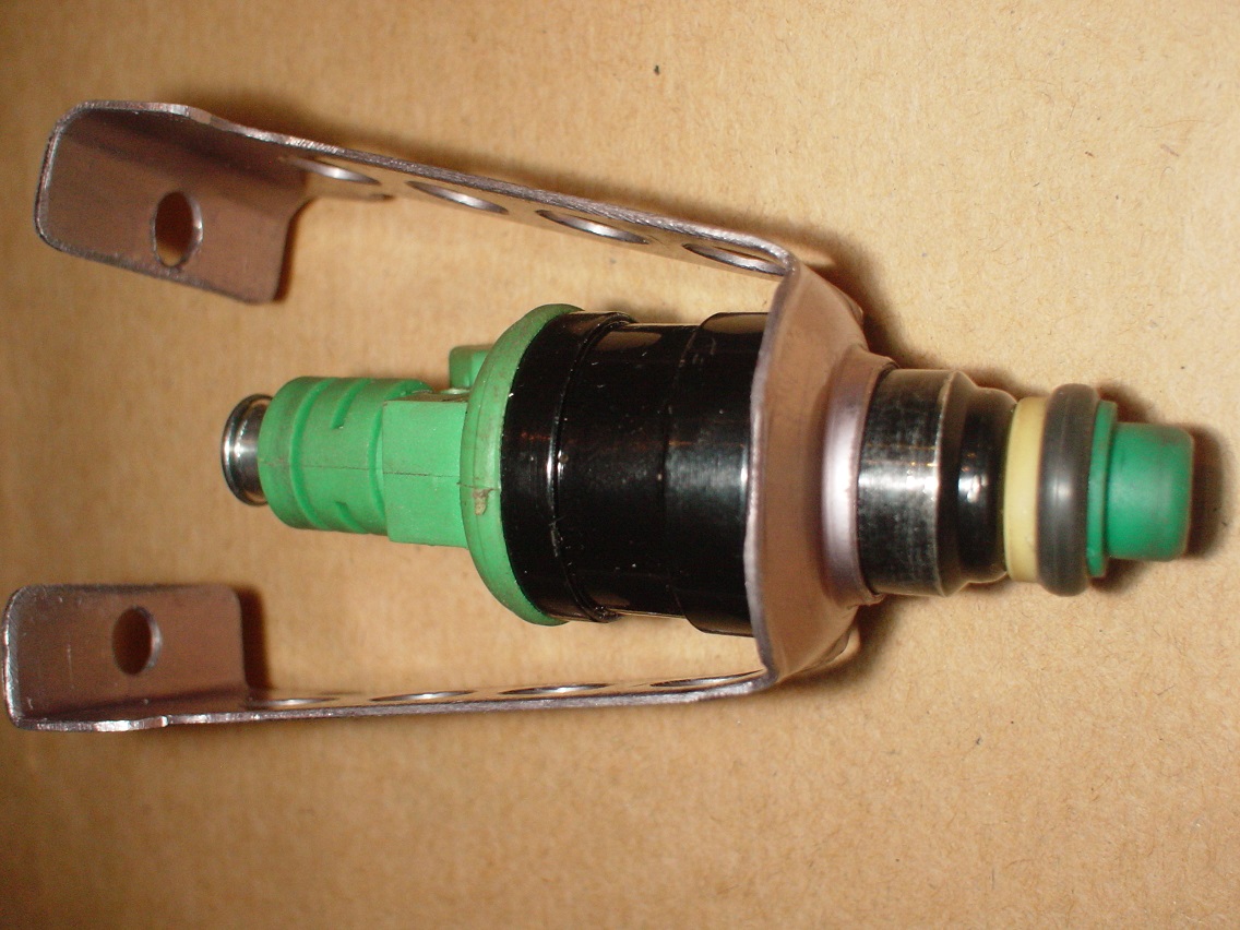
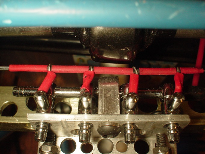
My injectors arrived, i chose 0280150558, these work with the cosworth fuel rail fit the pinto loom and supply440cc...perfect for my needs...
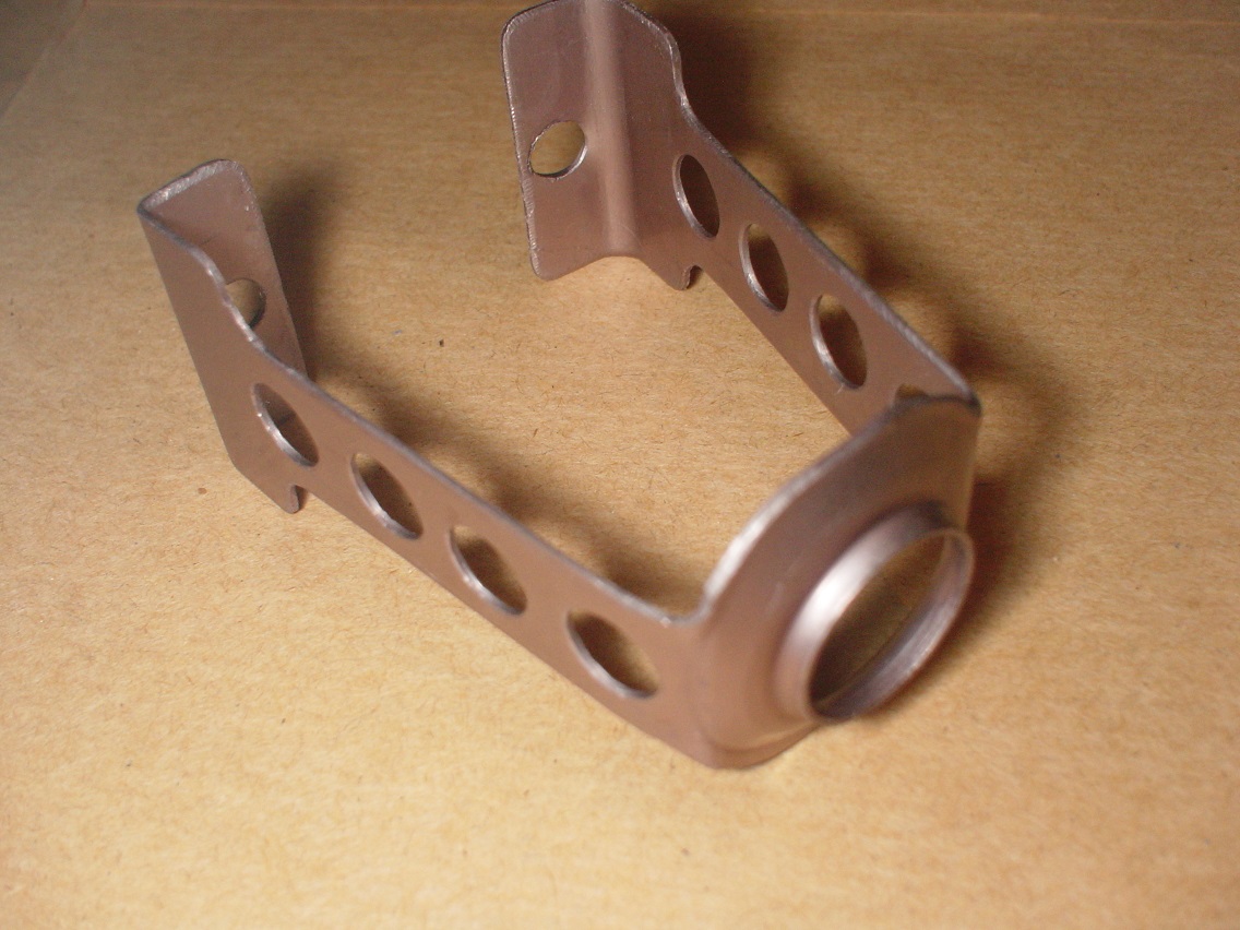
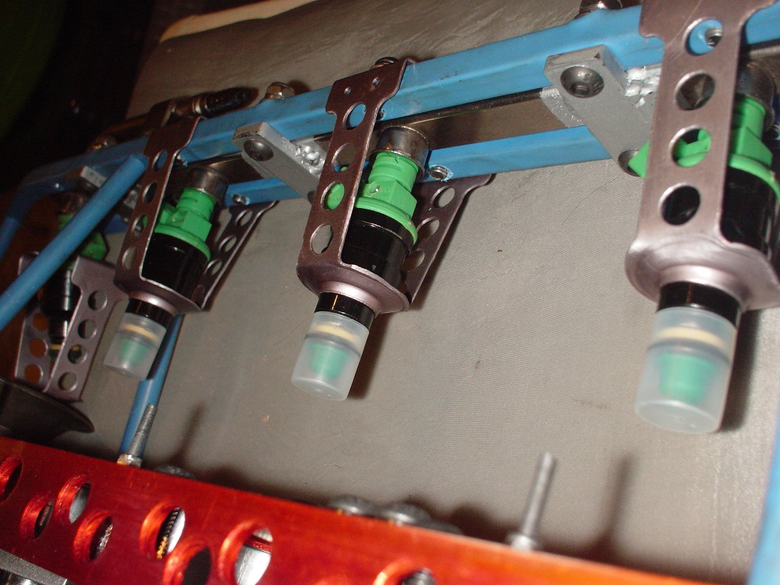
These are the top 4 injectors...sitting above the trumpets....so i wanted them to be fixed super strong but super light ...so designed a super light fixing brkt out of 0.9 alli sheet...
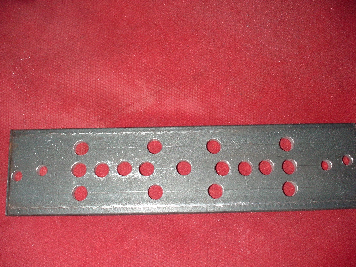
needed 4 off so made a jig to drill the brkts
cut the first shapes
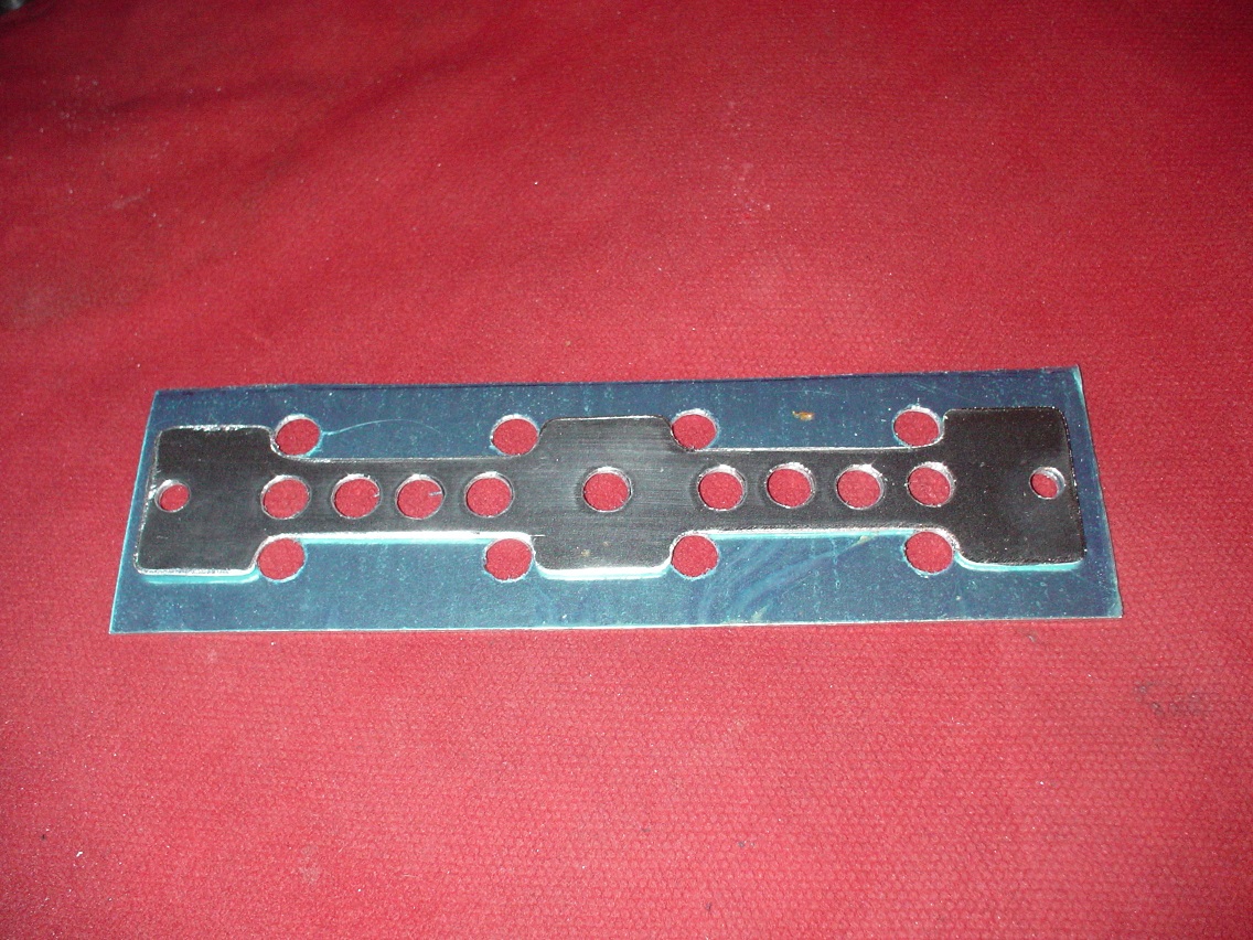
Then score and snap to shape
to give strength i gave it a double swage with a bit of bar and a hole...test part
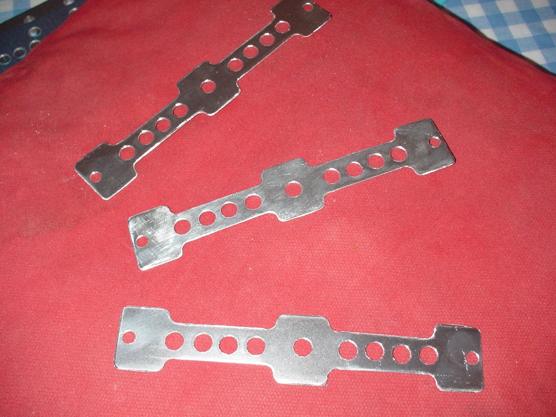
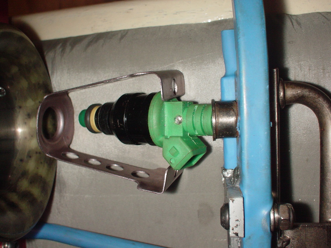
test fit
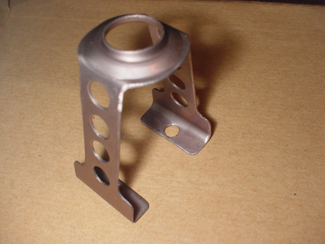
Worked a treat so finished the brakt and anodised them...pearl grey
finished bkt with injector in place..
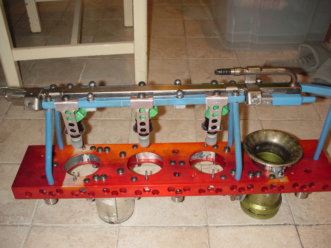
assembly
finish fitted...super strong and super light..
with all the parts ready i have started to final assy...being a bit paronoid i have tripple locked all the fixings (tapped/ spring washer/lock thread/spring washer/nylock nut)
the linear bearings installed..cam follower bearing installed and the first sliding stack installed
and in the fully open position
didnt have any time to buy any color die for the anodising so mixed the green and blue dot color with the blue (expected a brown) came out
purple
if you read through you will notice that i havnt finished the exhaust ports and valve seats,,,,,,
so started on these. i have decided to move the valve 0.3mm away from the inlet valve...but ignore rocker ..i believe there is enough free movement in the rockers to still align ok
so made a tool...
cheers mark (oops picks a bit big)
Hi Mark,
Those parts are really looking good.
I am liking the anodised look on the parts. I may have missed it earlier in the thread but what setup do you have to do the anodising. Also can you show a photo of the tool (bar) that you used to do the swage on the bracket.
Regards
Tom
To finish first, you must first finish
Hi Tom..good to hear from you...seems a long time since we talked about starting this..here is a link about my home annodising...http://www.turbosport.co.uk/showthread.php?t=579337...i will take a pick of the swage tool when i get in...
any projects on the go at the moment ?
cheers mark
it's looking amazing fella, really is coming together.
its not dead till it's buried!
T.I.T engineering. "Feel the power!"
Might I suggest hard wiring the aux. injectors as it looks extremely tight to fit / install 'normal' junior power plugs?
One question......how much power are you anticipating making if you are using 440cc / 400 odd hp injectors as auxillaries? or do you intend to blend from mains (close to valve) to the Aux around WOT?
Yes agree hard wire is the answer...want to blend...thats the idea...440cc good for about 350hp...i only aim for 200hp..if over injected i can go smaller..but after speaking to emerald we should be able to controll the fuel......mark
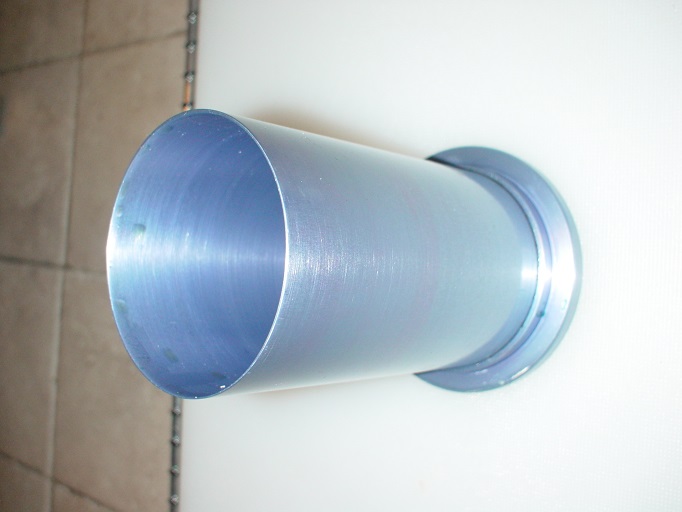
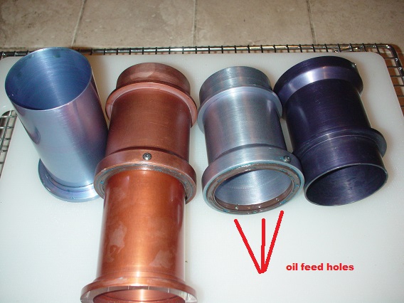
More progress.. finished anodising the stacks...tried brown....orange/brown and tried to make baby blue colors...i think i like the baby blue best so far
i wanted to make a oil drip feed system for the stacks to create an easier friction free system
so designed a system and tested it ..seems to work fine so started to make the real thing..
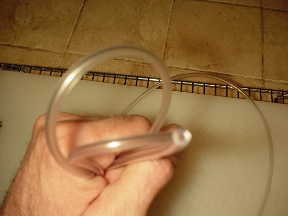
first i needed a manifold that would divide the oil between all 4 stacks...so i modified an aquarium air valve ..i can controll the oil in via the valves which i have linked and the 4 outlets go to each stack via some 2.5mm i/d tube
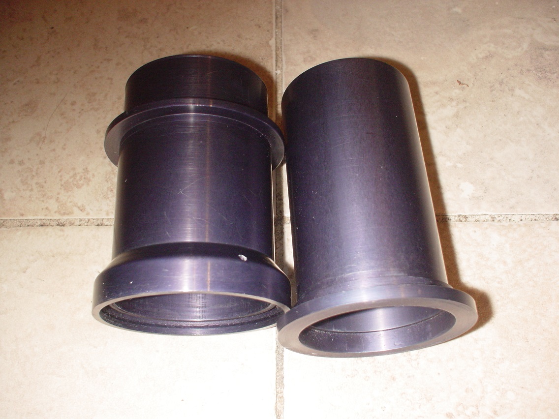
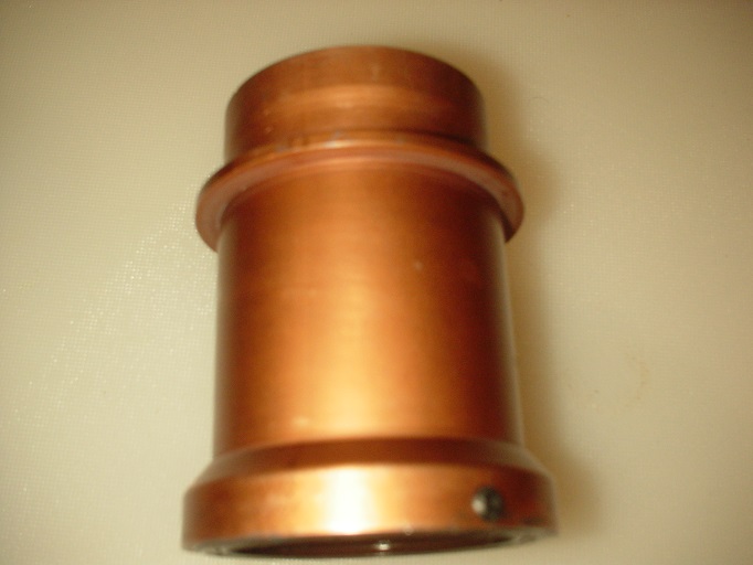
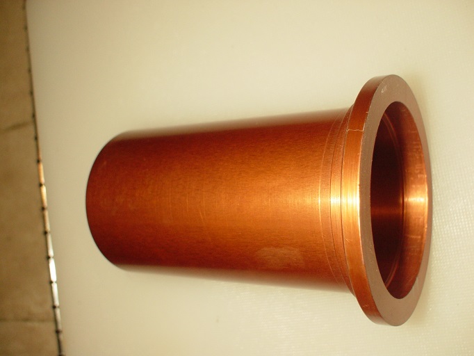
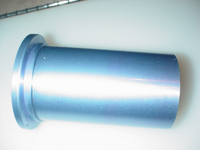
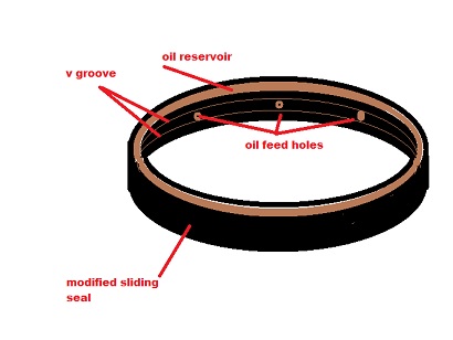
next i needed to modify the seals ..they need to store the oil(baffled reservoir) and supply to the moving parts without leaking oil into the inlet system
a quick sketch of the idea...
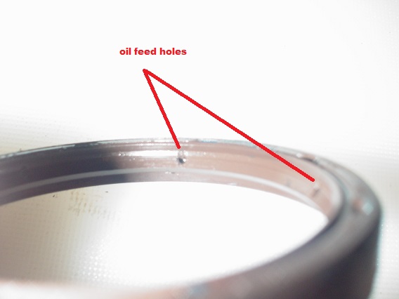
and the actual modded seals
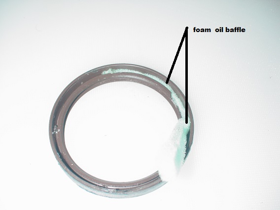
next cut some petrol/oil resistent foam and fitted into seal(baffled reservoir)
then sealed and fixed in place
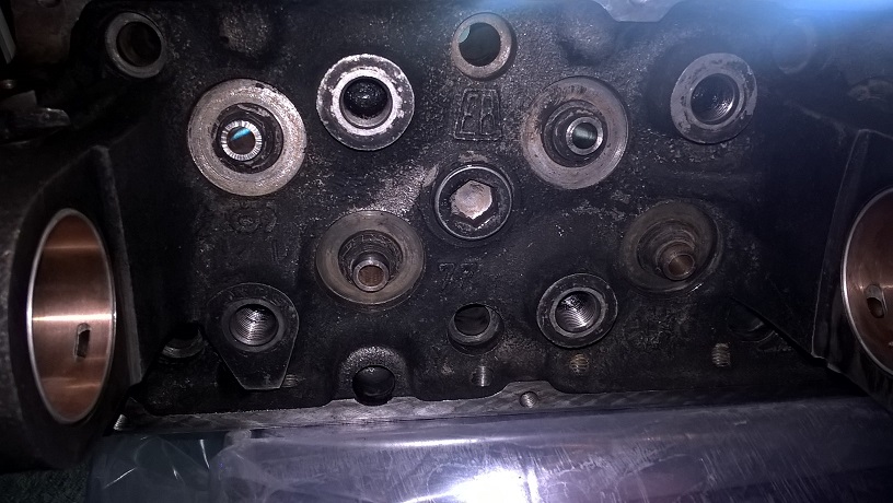
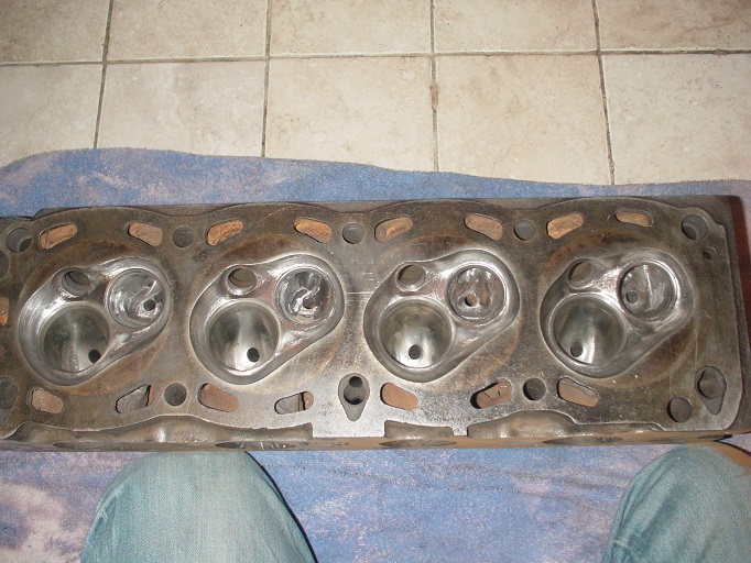
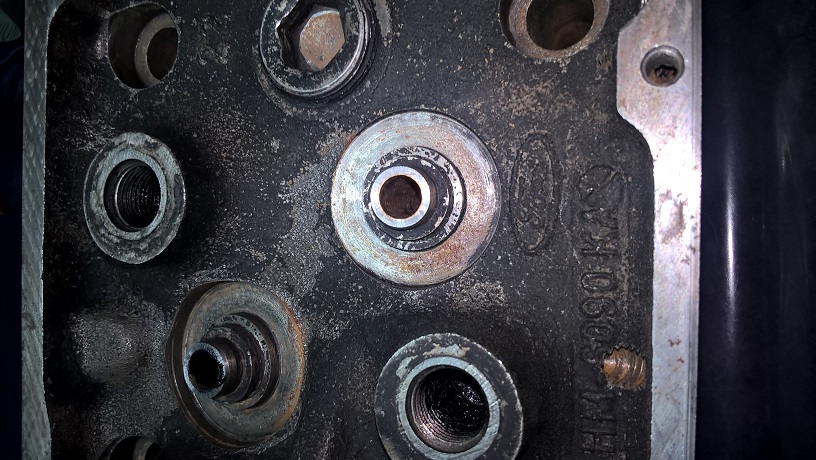
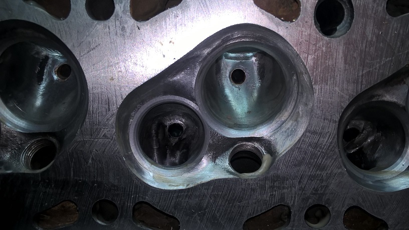
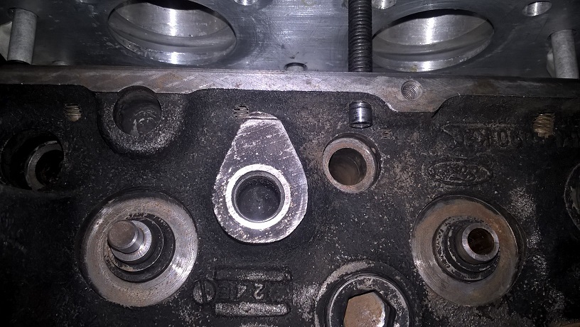
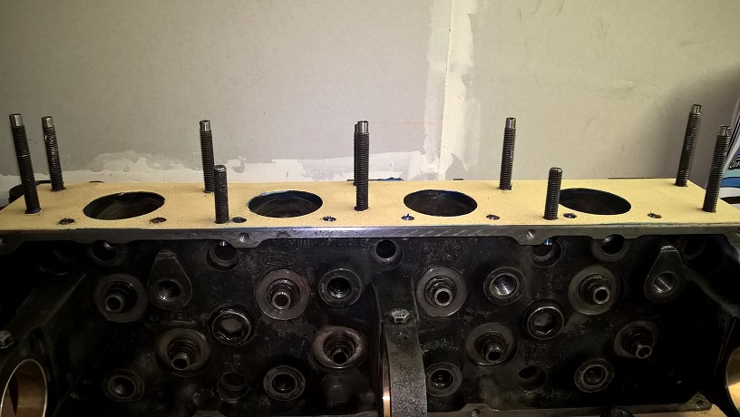
Having finally decided om what cam to run i can now finish the exhaust valves/porting
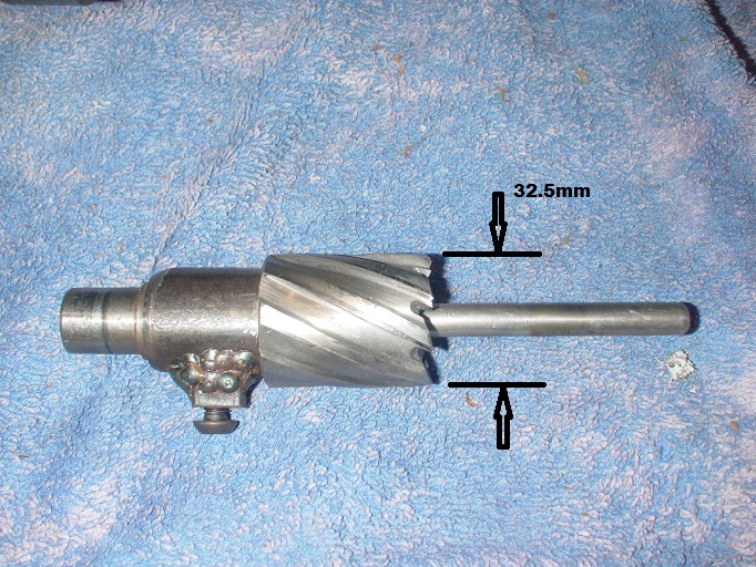
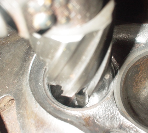
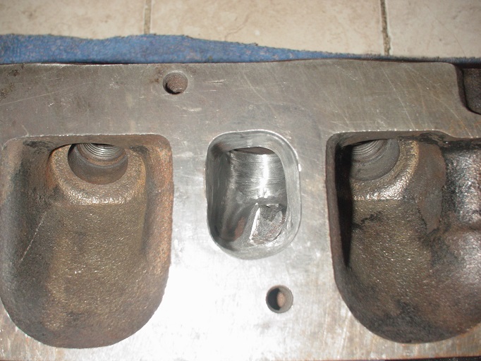
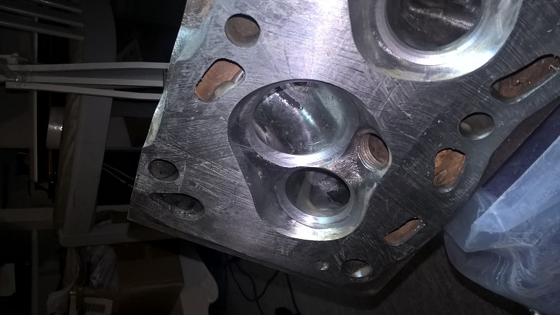
i made a tool to bore the bowl out to 32.5mm and bored all 4 out..the depth was jus below the short side turn...
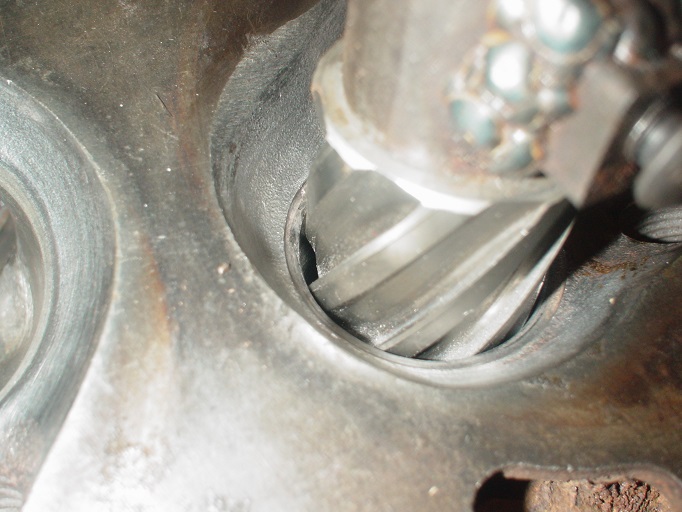
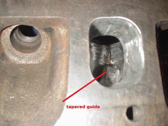
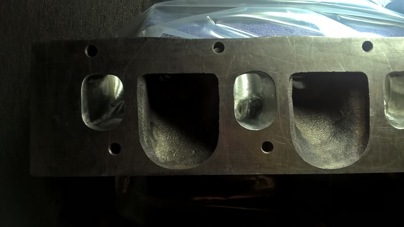
next i ported the exhaust port,,,short side turn.. roof and sides only(i was a bit nervous as i have no idea where the wall thickness is on the 1600 head) i kept an amount of valve guide and tapered it out...managed to get all 4 done to my desired dimensions without breaking through any walls
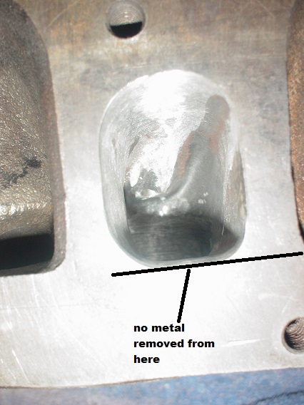
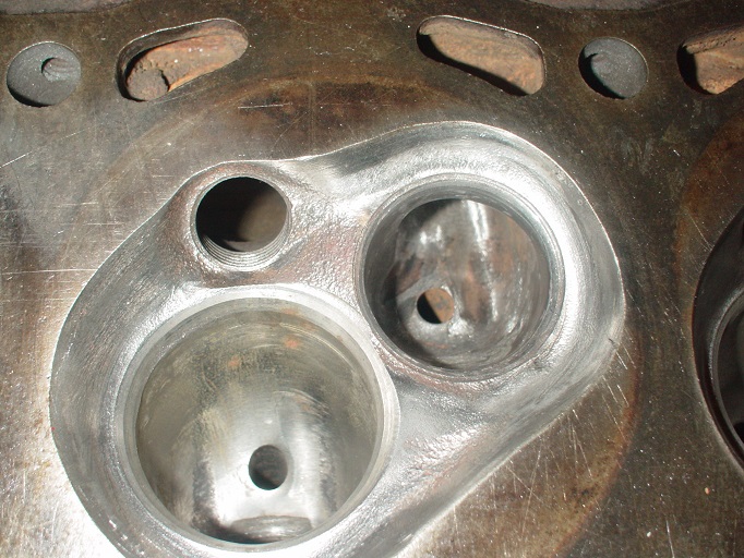
unshrouded the exhaust some more and did a bit of blending ready for the final valve seat cuts and the head skim
checking valve clearance closed
valves open (equal lift)
0.3mm clearance ....
next jobs fit the new valve guides ...spring height machine and skim the head...then time for final assy...cheers mark
Looking good i bet your getting excited now to see it all up and working. There's a huge amount off effort go e into this and i hope it goes really well.
Amazing work as usual. The things you can do with household items
To finish first, you must first finish
Hi Tom..thanks... as a side question do you still have the exhaust programme we used for the lightning rod....i would like to run some numbers for this engine for a manifold and exhaust system.......im thinking 4-2-1 manifold and side exit system.... cheers mark
Hi Tom..thanks... as a side question do you still have the exhaust programme we used for the lightning rod....i would like to run some numbers for this engine for a manifold and exhaust system.......im thinking 4-2-1 manifold and side exit system.... cheers mark
hi Mark. I still have the program and would love to run the numbers for you. Let me know the specs, cam timing and the revs you want to run and I will do the calculations.
To finish first, you must first finish
Thanks Tom...ill post specks here for all to see...
Bore...93mm
Stroke +2mm...78.95mm
Rod length 144.5mm
C.R 12.8:1
Cam Events
Exhaust open 82 bbdc.......close 54 atdc
Inlet open 54..btdc.......close 82 abdc
duration 316
inlet valve 46mm
exhaust valve 37mm
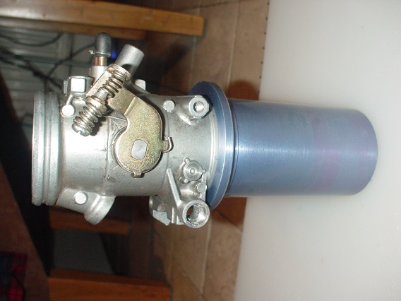
46mm throttle bodies
max revs 8000
running an emerald ecu...so timing//injection ect should be optimal
cfm is more than when we tested..(your best guesse)
any more info required let me no..
Cheers mark
Any updates? really enjoyed reading this thread
Yes..been a bit busy building the car for it to go in..mk1 escort ratspeed ...will get the pics together and post later next week...
cheers mark
Wow cant believe its so long..where does the time go...
so before i stripped it down i did a dry run of the veriable velocity stacks..i set up a simple timed switch..and ran it for 5 hours on 20 sec inpulses ..so up and down 3 times a minute for 5 hours= 900 cycles..
It ran no problems.....but on strip down...the tool steel guides had grooves worn in them from the roller bearings..you couldnt see them but you could feel them.....then i remembered i had'nt case hardened them..(was going to do it later) i now need to make some new guides...
also on assembly the velocity stacks need to be dead on parralel/straight up...and with the best will in the world they were good but not dead perfect...so to get then dead on, i converted my surface grinder to a surface sander...so after assembly of all the throttle bodies ect i can whip the surface sander across the tops and get a 100% dead flat and parallel surface for the stacks to sit on...will take some pics of the surface sander next thurs day...
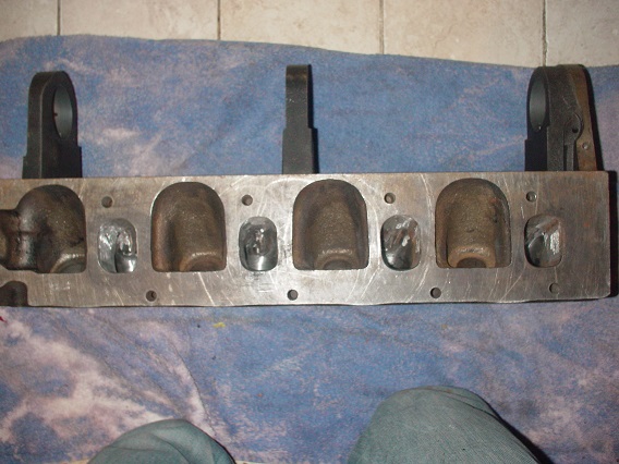
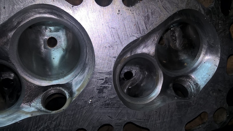
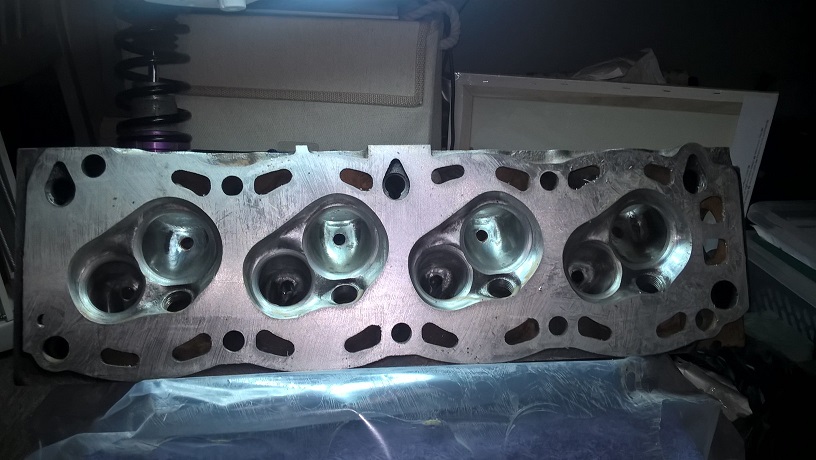
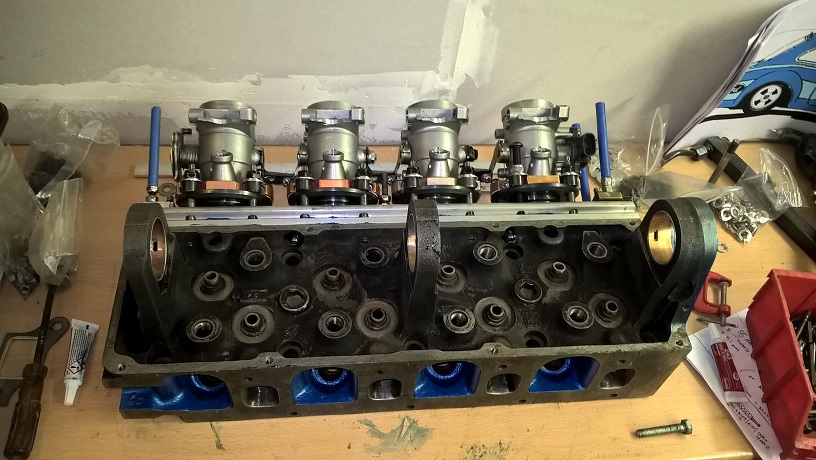
so finished the exhaust ports now all the same...might give them a little finer sanding but i think they will do as is..
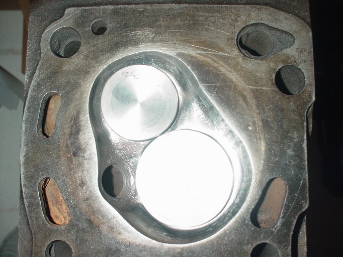
i then fitted the valves and did a cc calculation...
I had 40.0 ccs...was expecting higher so pleased..
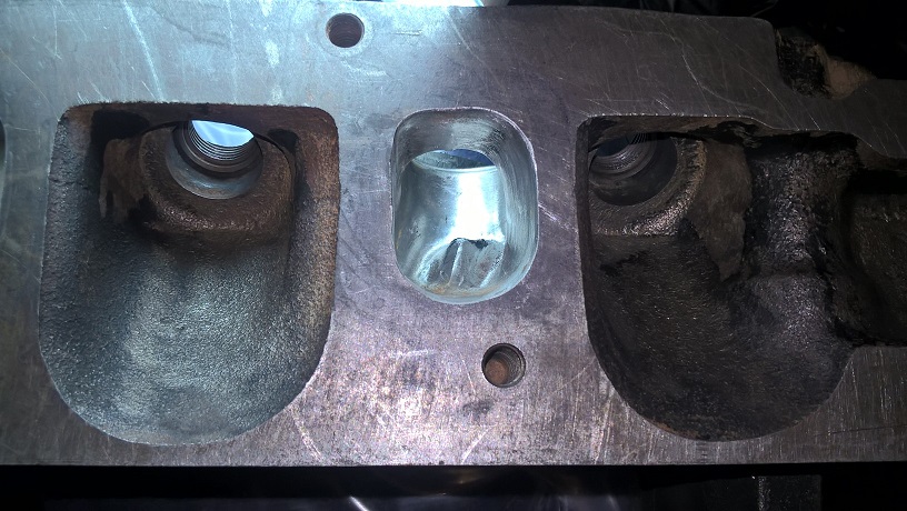
thought i would have to use bullet guides...but on closer inspection i could use k line..so fitted k line guides...
i matched the tops of the guides with a little cutter ..to get them the same and cleane the tops
now i could final cut the valve seats...i used the same cutters i made earlier...but did it much more carefully and it took ages...
re fitted the valves and cc again now 40.3cc so worked out the amount of skim and borowed my mates mill..(i want one )
skimed the head to 36.8cc which will give me a compresion ratio of about 13.3 to 1...
my finished goal is 12.8 to 1...there is plenty of finishing work to blend and unshroud a bit more...i will take it to 13.0 to 1
and try the engine...i can always take a bit more of...
while i was at my mates workshop (its got heating) i fitted the cam guides...
cheers mark
Freaking amazing
Thanks matt...its a big learning curve for sure...cheers mark
Incredible work !!! Best of everything known exercised here I imagine and you went even much further than that.
Look forward to seeing the result.
What is the camshaft ? Is it a one off grind or off the shelf ?
Hi its a one of grind....that i tried with a 2ltre head...about 8 years ago...but couldnt get enough compresion...
its perfect for this build..hence why i used an early 1600 head...ill post the spec up later when i get home if you like ...cheers mark
Hi Mark,
I would very much appreciate. Thank you.
Going this much down draft certainly needs throttle bodies, right ? Carbs would not work this angle.
Of no comparison at all to your engineering projcet but I am sure, I will want to try shallower angle down drafting which could work with the carbs. I can still use your sealing method though, can not I ?
By the way, could be great if you could change the topic name of this thread to ... Shed build ENGINEERING.
Once more, incredible work. BIG CONGRATULATIONS !!!
Cheers,
Kerem
Thank you...yes the sealing method would work.....i think if you fitted a matched carb manifold then you could get carbs to work at my angle..the problem will probably be space to fit it....we can steal a couple of degrees by tilting the engine...but then a dry sump would probbably be needed to controll oil...be a good project....another member " memphis" was doing a same but different idea...he epoxy the tubes in and would end up with a flush manifold flange...dont no if it worked.....cheers mark
Thank you.
I will study all the details of your work and also Memphis's over and over again before attempting of course.
Yes, the space is a problem in the Escort but as you said with a matched custom manifold might work to a certain extend. Tilting the engine requires some work all around but Dry sump is not a problem, I can use it.
What was the ideal total lenght required from the bellmouth to the valve if this was a non velocity stack, carburetors project that I must base everything on ?
Cheers,
Kerem
Hi Mark,
I thought my ears were burning!
Are you going to get valve pockets machined into your pistons? I'm sure they will be needed when using a skimmed 1600 head with any decent performance camshaft.
I shelved my downdraught head project because I couldn't get enough compression on the 1700cc bottom end. It's all complete, brand new, all bits ready to assemble. All that's lacking is a camshaft. I ended up with chambers of (if I remember correctly) about 39cc, but because of the unshrouding required for the 45 and 38mm valves I had to skim a lot off the head face. I think I shaved about 3mm off, which brings the valves close to the head face (only about 4.5 to 5mm clearance) so will need at least 3mm deep inlet piston pockets and 2 ish for the exhausts. This would have lowered the CR even further on the 1700 bottom end, so I just gave up and am now building a hot Crossflow.
However, I think on a large capacity (2.1litre) the head would work brilliantly. If anyone reading this would like to experiment with it free of charge, then they can just send me a PM. I will not now be using it, but I am very interested to see how it would go. This would be entirely at the user's own risk, and no guarantees are given as it is an experimental build. I designed it to use with Keihin FCR downdraught race carbs (now sold), but it would work with Webers if a nicely curving semi-downdraught manifold was fabricated. Not rocket science! Pictures can be seen on my thread " 1700 pinto Back On" in this section. Sorry to hijack your thread Mark.
Keep up the great work. Cheers chris.
Once again, apologies for hijacking your thread Mark. My downdraught head has been earmarked for a regular contributor to this forum, so is no longer available. Thanks and apologies to everyone else that expressed an interest.
Cheers Chris.
Hi no problem...was hoping the head was still ok......interested my self to see how it performs....cheers mark
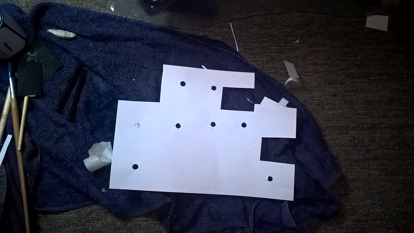
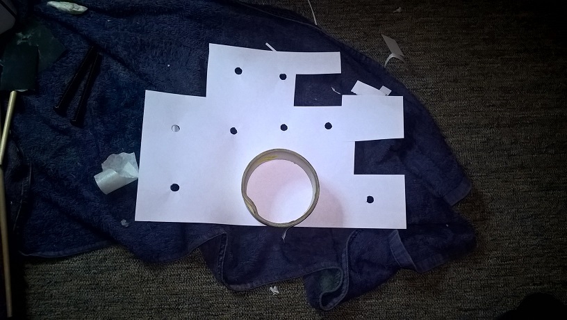
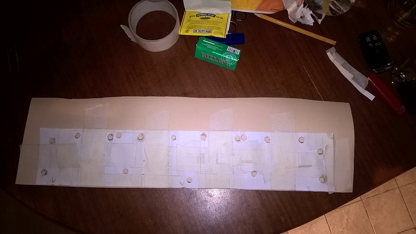
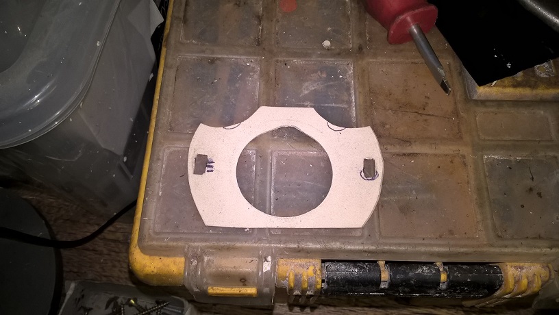
Needed to make a manifold gasket...as mine is totally unique...so got a roll of 1mm petrol/oil resistant gasket paper..and tried to make the gasket by holding it on the head and getting an imprint...because ive got so many fixing holes the results were crap...
so plan "B"... i made a quick 8.5mm punch using a drill( drill a hole in a bit of plate with the drill of your choice...remove the drill ...grind the shank flat ..put back in chuck upside down and you have a punch and die) .. so punched about 20 holes in a couple bits of paper...
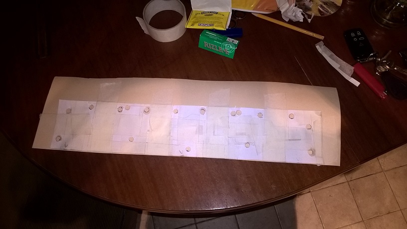
cut the paper into squares with a hole in middle...then placed each square over each hole ..place a bolt through each hole to keep aligned..then using masking tape join together....
removed...taped to the gasket paper..
now i just have to punch the gasket using the template as the guide...
cheers mark
Inventive as ever
To finish first, you must first finish
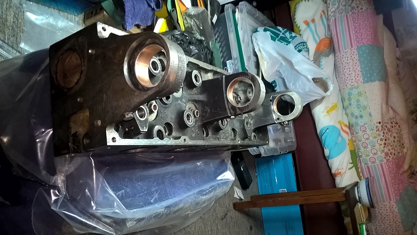
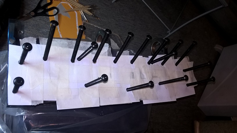
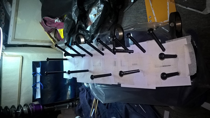
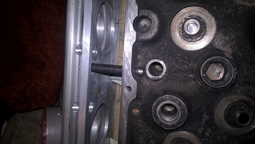
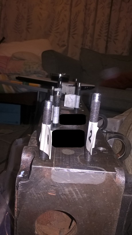
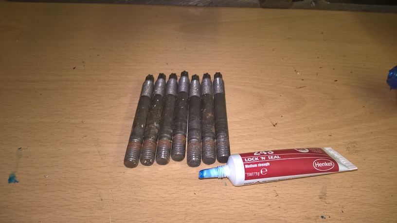
Planning final assy... needed to get some manifold studs...i assumed it would be easy to find grade "10.9 m8 studs" in different lengths..but of course not......so had to make my own...was lucky and found a box of 250 0ff " 10.9 x 100mm old stock full thread machine screws" for £5..
So decided to make my own...i kept the allen head on the bold to aid insertion..and turned the head down so the nuts would clear and cut to length..
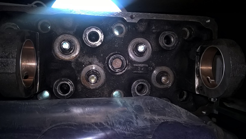
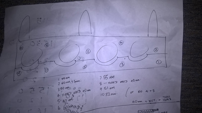
i wanted to go full depth on all the bolt holes...so measured the depth and came up with finished sizes... the plan when all bolted down to have same amount of head showing...
the plan
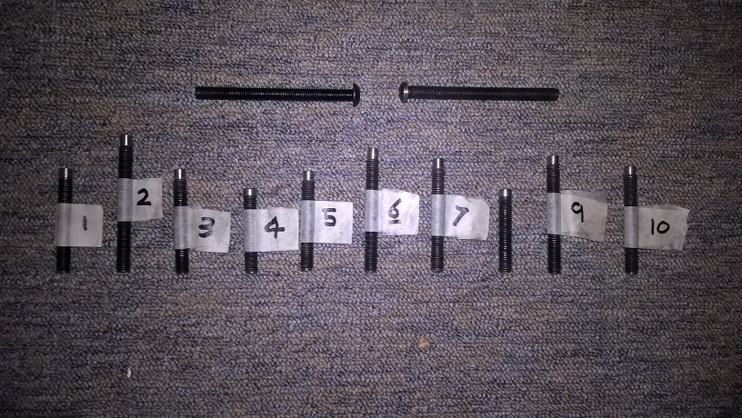
Bolts "4" and "8" are reverse fittment from inside rocker...(there isnt room after assy)
I chose the strongest wall thickness i could get near to...but still had to clear the head bolt for clearance...
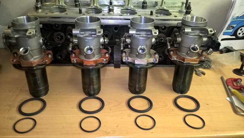
Just waiting on some new viton 75 "o" rings 39 x 3mm to turn up ..then i can start assembly...
cheers mark
Im always in awe of your skills.
Thanks Matt..Lets hope it all works....mark
So impressive....
Thanks shaun...
cheers mark
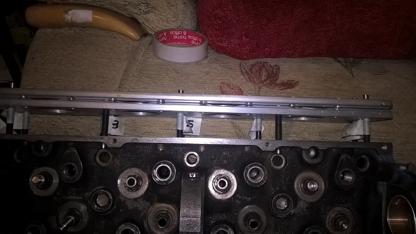
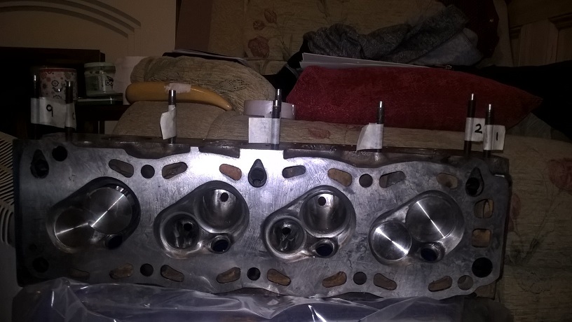
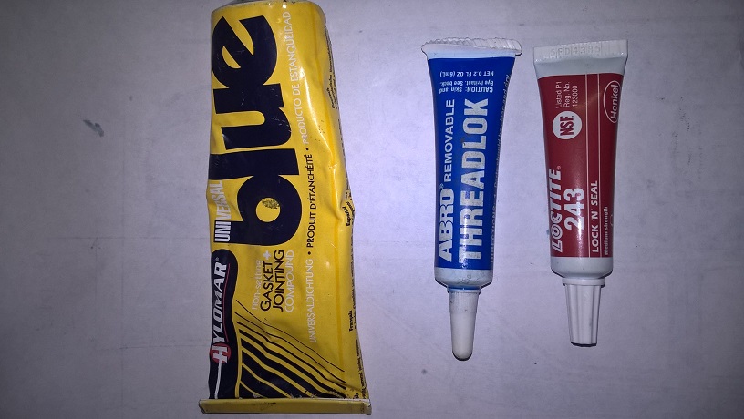
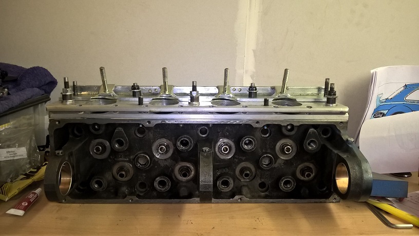
Small update...time for final assy...
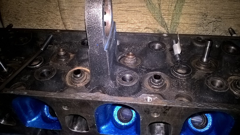
Im using blue hollimer/thread lock and lock and seal..for the assy..
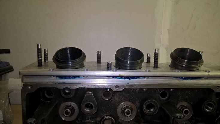
I locked and sealed all the studs in place first..then applied blue holimer to the head then placed the gasket and clamped in place..
then removed clamp and edged the ports with blue hollimer and placed the lower manifold in place..
......
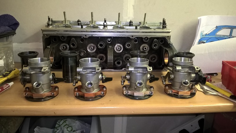
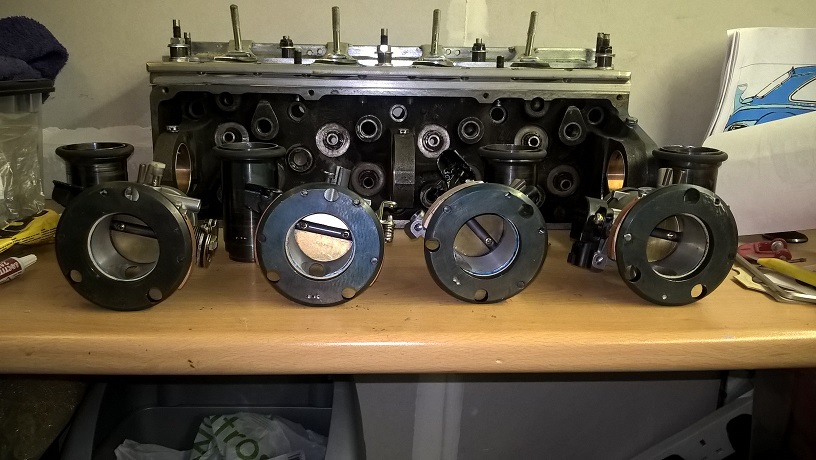
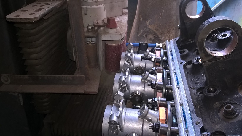
I had already made each sub assy of the throttle bodies and clamps..cutting gaskets and final fixing each part to its mating part...making sure all the ports matched exactly..
All ready for final assy with new viton o rings..
The next part all has to go together at the same time..before any sealer sets.. so was a bit involved..
Finished all ready for final fine tune maching....cheers mark
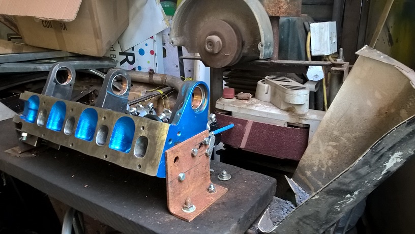
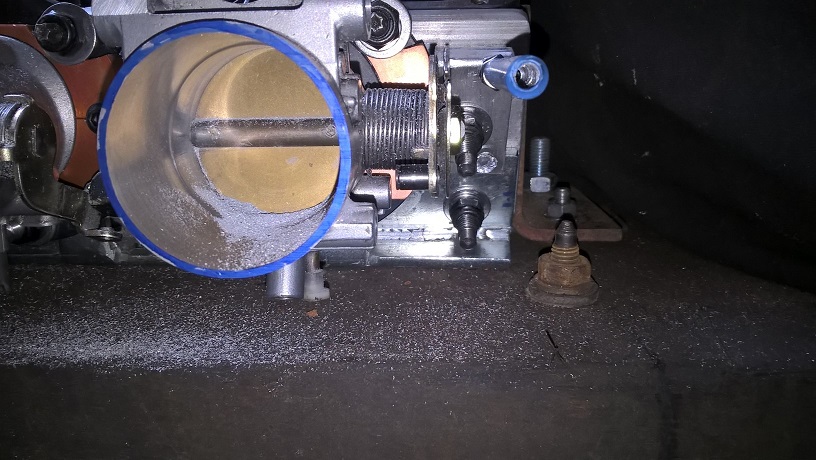
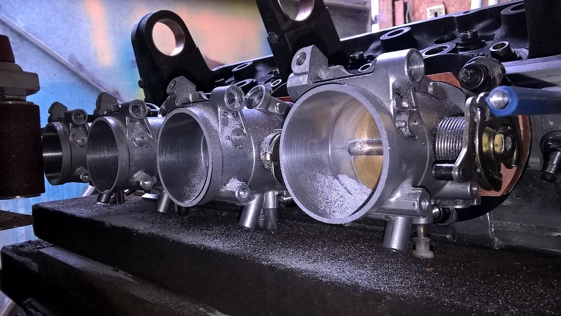
The next stage is to machine the top of the throttle bodies.on the assembled head...this will give me and exact/flat and parallel platform to build up from...and removes any building tolerences..
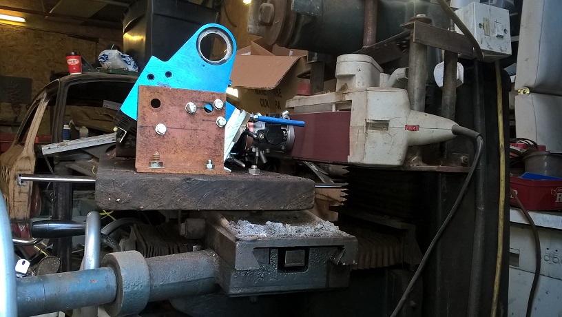
So made a modification to my surface grinder..and its now a surface sander....
Made a clamp table out of a bit of old hard wood...couple of clamp brackets at the correct angle...all bolted up ready for surface sanding...
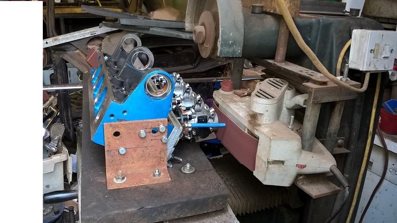
After a couple of passes i" blued the tops" and made a finish pass..to check that all was good..
And finished
Ready for the next build up..
Cheers mark
 Posting Permissions
 Reply With Quote


Bookmarks