


Amazing work

Amazing work
Impressive stuff going on here... Whens the next update
CheersOriginally Posted by Peanut1
im back on it tommorow...
so friday hope....cheers mark
Time for the steering/suspension.control arm fabrication...
couple of strengthening panels finished first...the centre section of the front frame...(will do the top after ive welded the fixing points)
ive finished reaming out the holes for the rose joints..
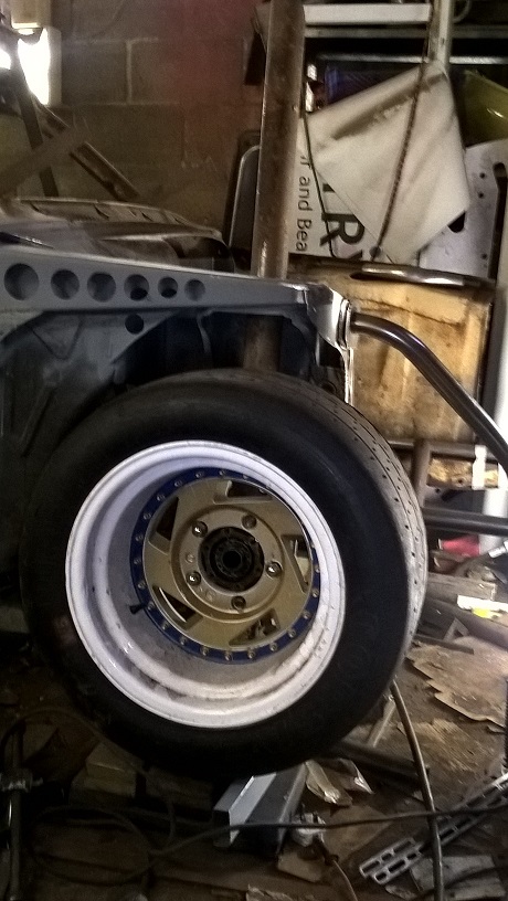
mocked up the front wheel at ride height..
after many hours of line calculators ect ..
my suspension position starting points are ...4 deg camber....5 deg caster...zero scrub radius...roll center of 128mm...zero bump steer..ive got
6" of suspension travel 3" up and 3" down or whatever i decide...and this is with 4" of ground clearance..
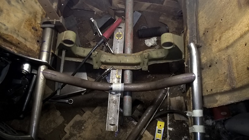
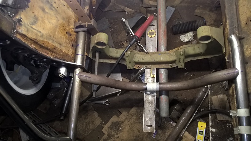
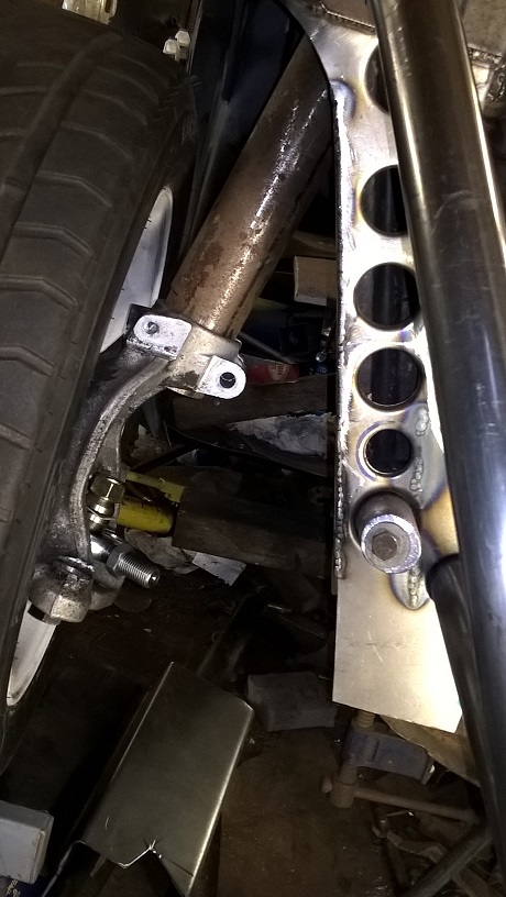
ive made the cross brace for the front frame and this will also br the inner pivot point for the front control arms
Ive left the crossmember in position for now...i wont be using any of it...my rack will be mounted in a different plane ..the engine will be chassis mounted...and the controll arms are chassis mounted as well...but i will still make a light weight replica just to give the frame rails some rigidity...
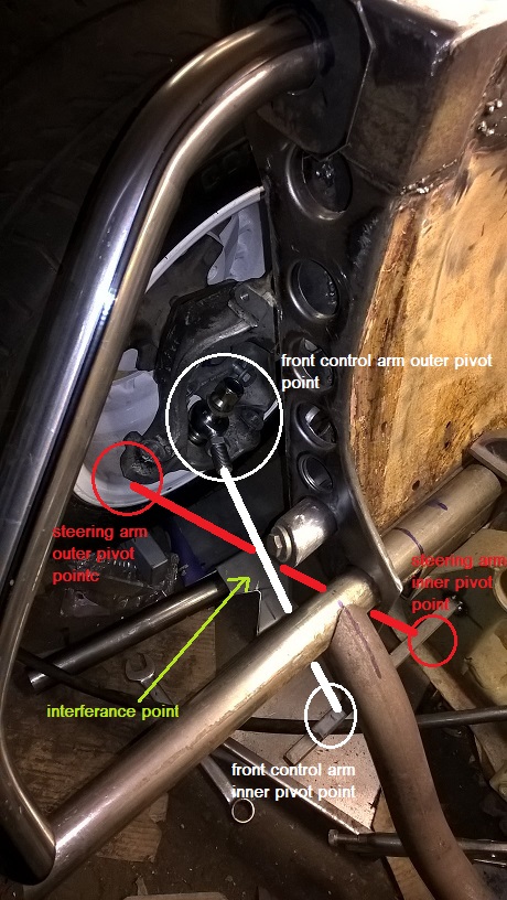
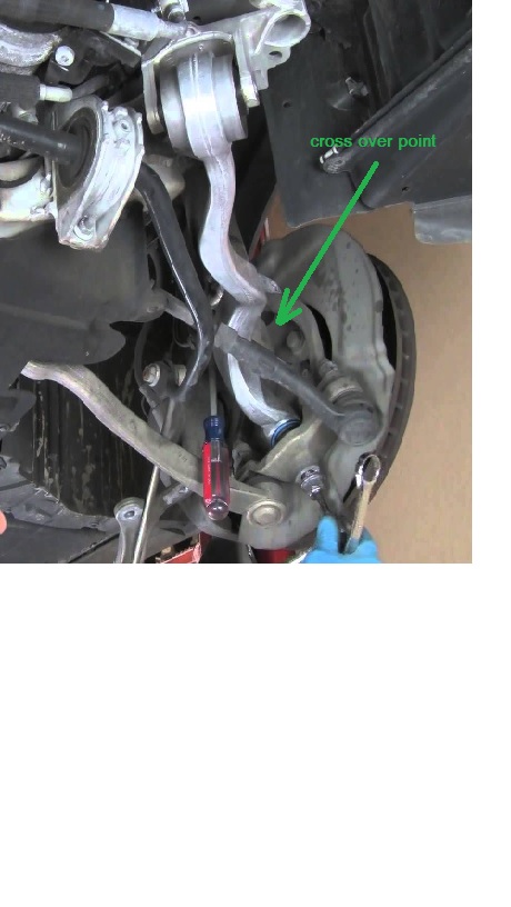
Ive marked on this pic the approx position of the steering arm and the front controll arm..
you can see they both want the same space...this is bmw answer...
i will have to put a bend in the front controll arm to miss the steering arm ..so ive gone with a twin walled tube to give me the extra strength back the bend would require...
ive started making my front struts from some leda legs i had...(no pics yet) but for the meantime ive used a piece of tube for the front strutt.
The other thing ive been looking at is the exhauste 4 branch route out of the engine bay....my plan is to take it forward then over the wheel on side the wing and down the inside of the outer sill...not much room..but a great challenge..
think thats where im at at the moment...cheers mark
Great stuff mate.
Really cooking now!
Thanks matt....one step forward at a time....get there in the end...
cheers mark
Any updates mate?
been working hard..but not a lot done...will post up some pics tommorow...
hows yours going....
any luck with the wing...been trying to work a schedule to build one for you..
cheers mark
Slowly too...
That wing you put me onto here in Oz (http://www.ozwindengineering.com/Products.php) would be perfect but the cord width is only 162mm so I'm thinking it won't be wide enough to look period correct.
If you do build one for me there will be a place reserved for you in Heaven!
Cheers,
Matt
)
I think your correct.when i made mine i thought id made it to big...but now i wish id made it bigger...its hard to judge untill the rst of the car is built...and of course the racing rules dictate on size height and position....i cant have anything further back than 100mm from the furthest point of the car...so i couldnt have the rear wing hanging like the capri zaks....
well talk and get some sizes ect...cheers mark
Thanks Mark. Chat soon. Matt
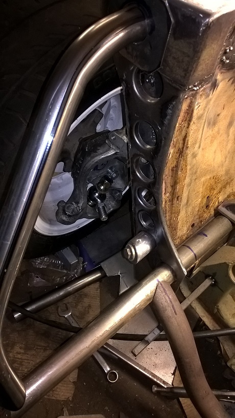
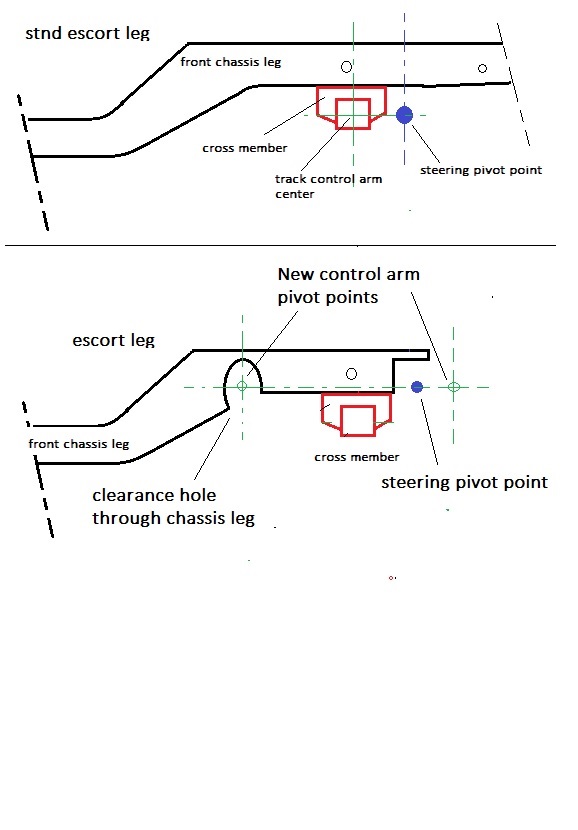
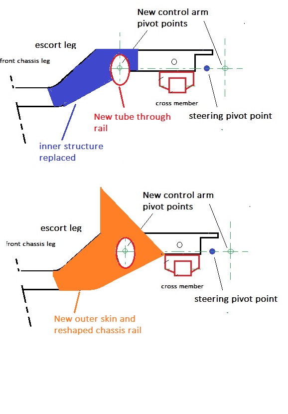
Been busy redesigning the front chassis rails....my suspension control arms pass right through the chassis rails ...and into the engine compartment...
so i need to re-route the exhaust..no room any more
and tube the chassis rail and replace the strength...i used 2mm steel double plated as original...except on the engine bay compartment i used 3mm because my control arm mount will be hanging of this..
a couple of drg to explain...
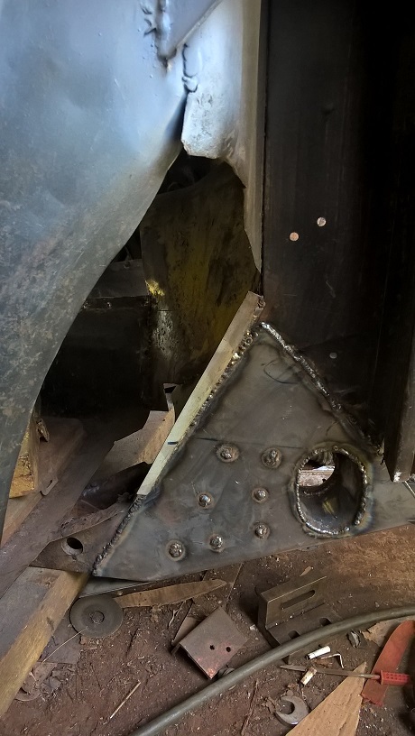
you can see when the metal is removed not much chassis rail left..
the plan
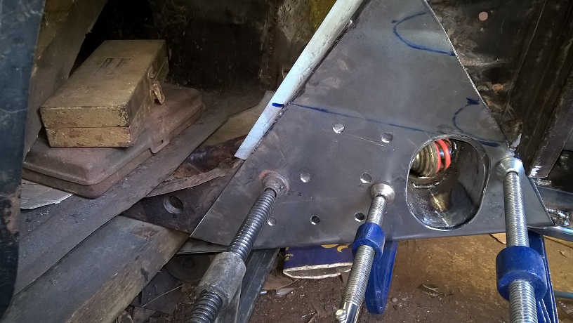
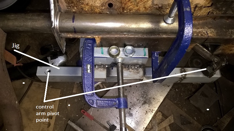
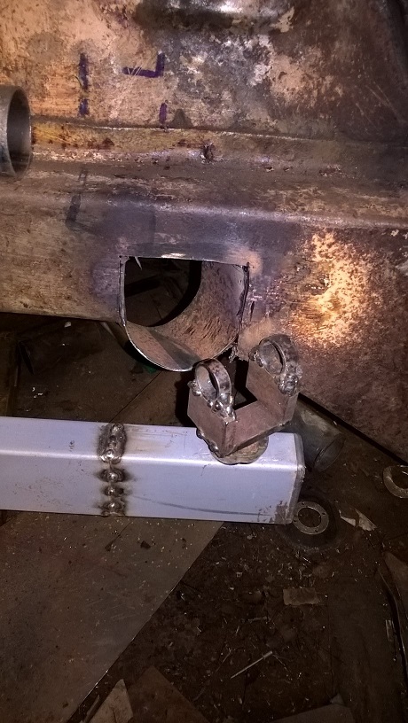
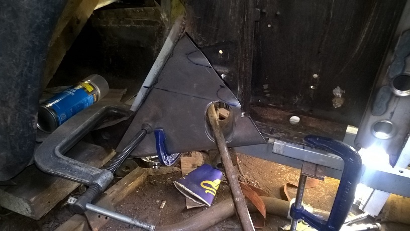
before i started cutting i made a jig with my new suspension points and made a quick joint with a mock up arm....
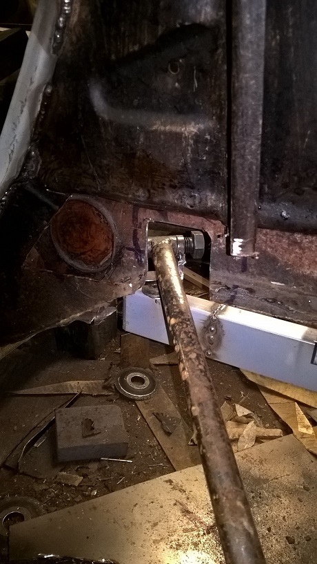
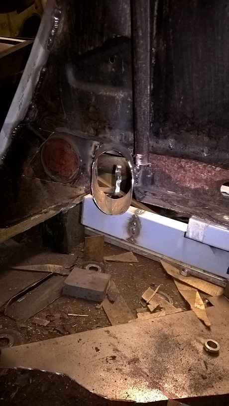
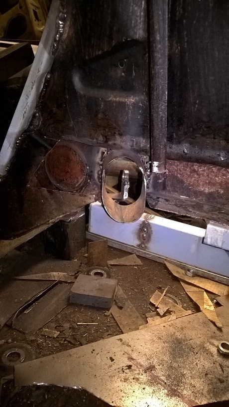
i then cut all the rust and clearance holes out..
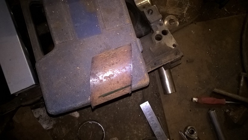
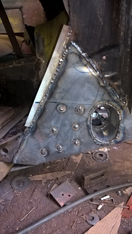
i then made an oval tube to fill the hole
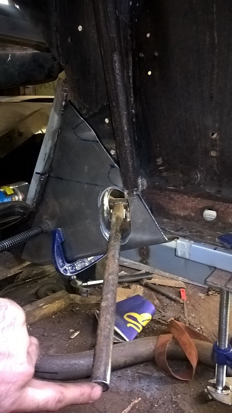
you can see the engine bay side ..needs a smaller hole because the movement is less...and i wanted to keep as much strength as poss
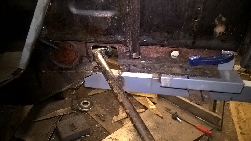
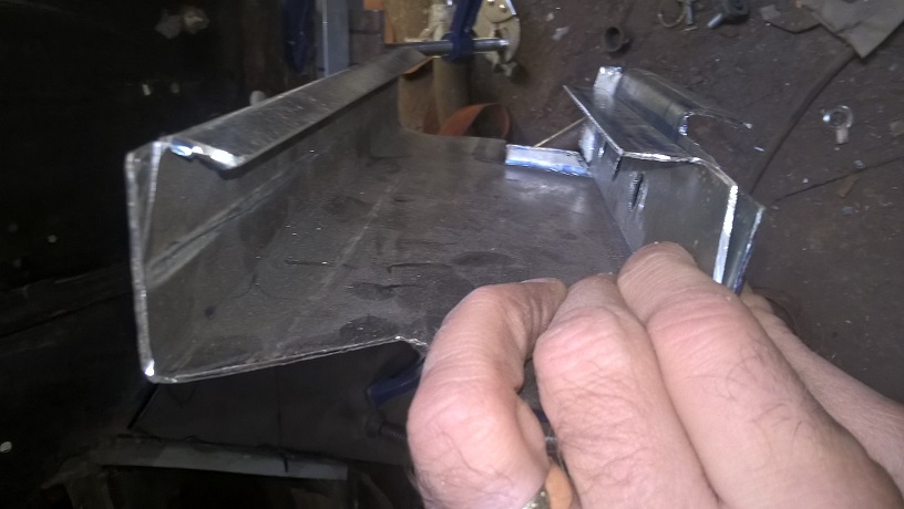
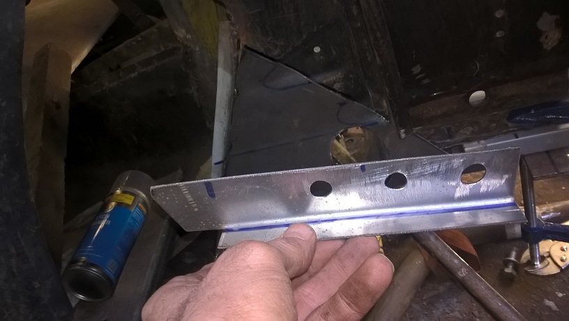
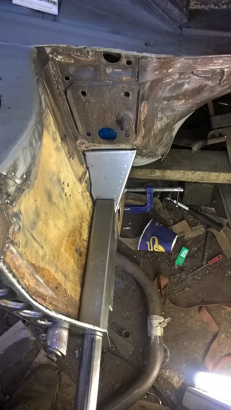
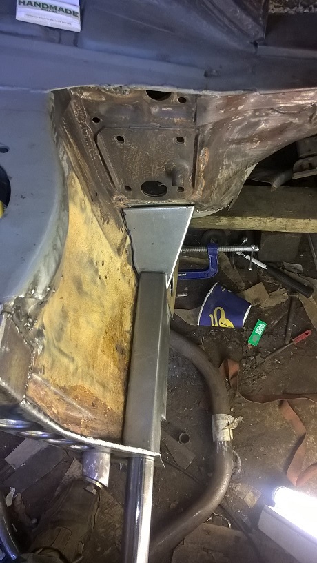
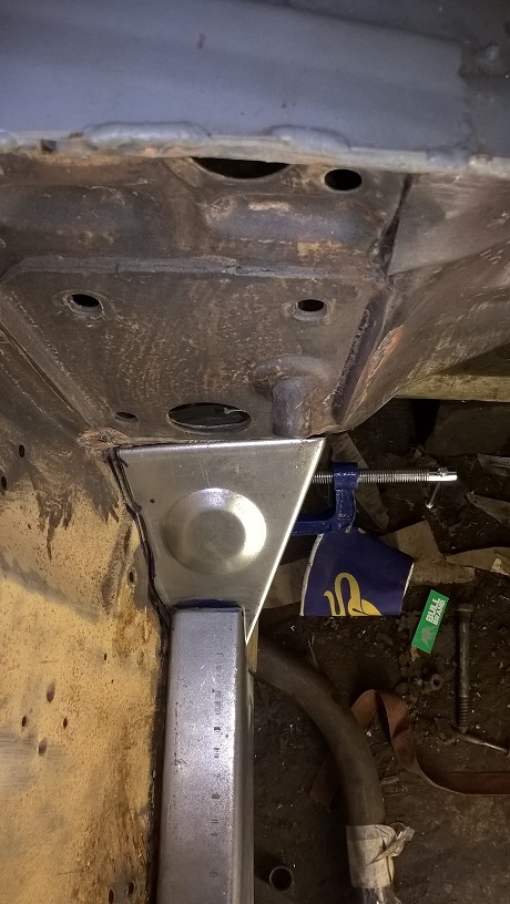
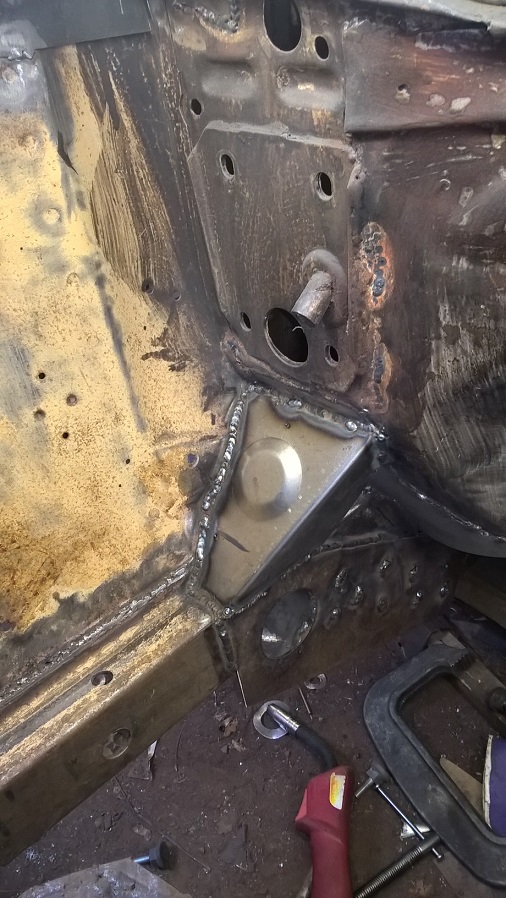
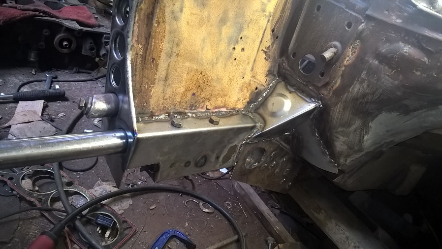
new inner plate made and welded this creates i mid box section up to the tube..
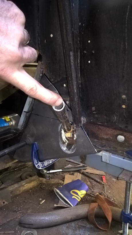
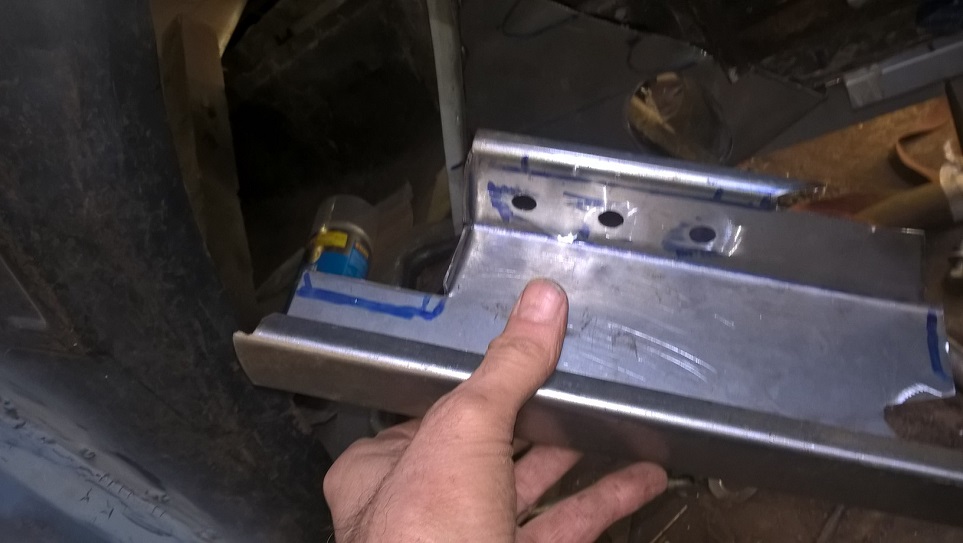
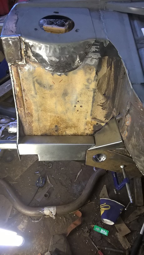
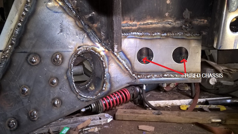
new outer plate made with new chassis rail shape..it also matches the engine bay gusset and ties as far forward aspossible.
checking for movement...i have 8.5" of total travel of shock..which should be ok..
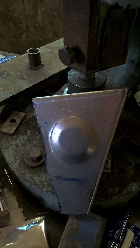
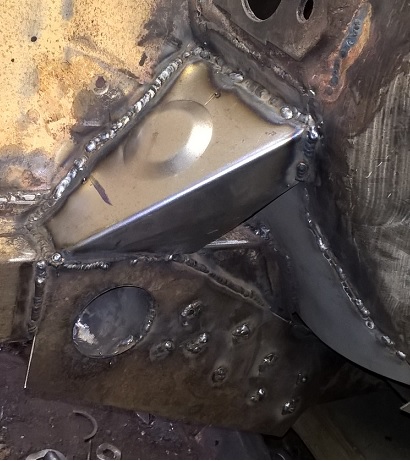
the engine bay gusset..
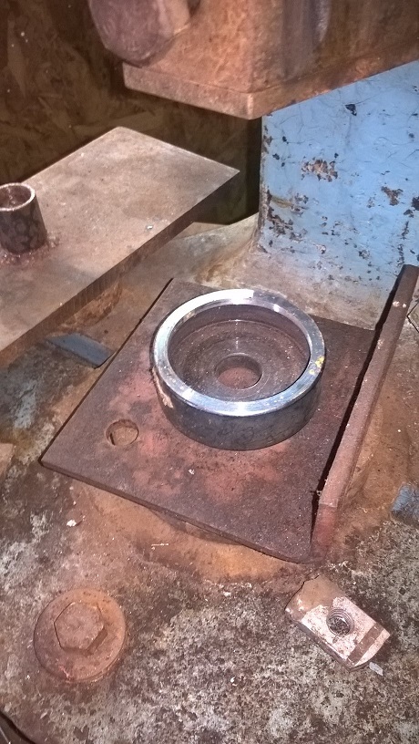
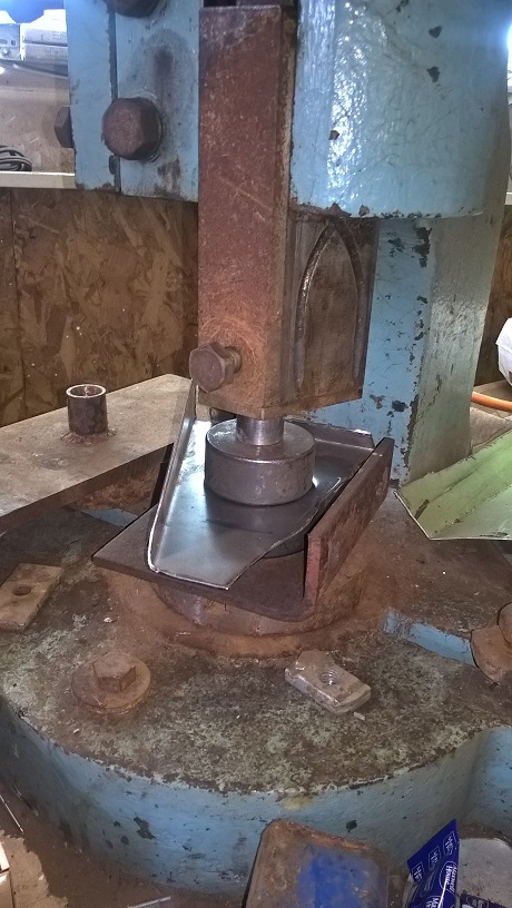
i wanted to put a strength dimple in it... so made a dimpler out of 3 different dies and a bolt and socket..
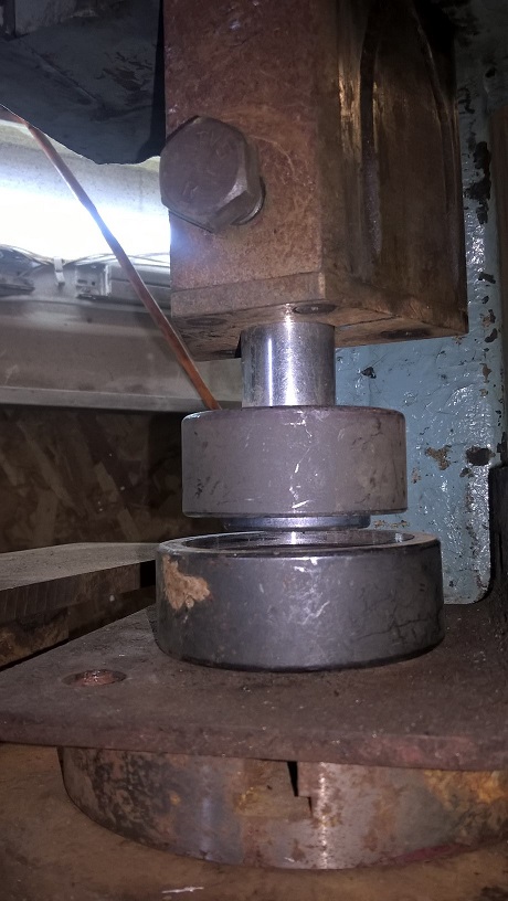
whacked it in the fly press
came out spot on..
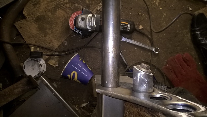
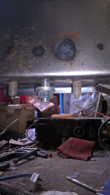
i am going to tube the chassis for the crossmember but i am going to extend the bolts ..so they bolt the new tubed front chassis rail (which will be tubed...(a tubed tubed chassis)..
so lots of bending ...measuring and drilling holes...
so pretty much ready for welding...
cheers mark
hi mark i would like to nominate you for some turbosport style points
Love this build.... A lot of work going into this
Thanks mate ..
Its amazing how it "esculates".just keep on changing/adding as it progresses...
cheers mark
Awesome stuff as always.
Your build reminds me of this build on YouTube - https://youtu.be/7hCPODjJO7s
Lots of good ideas and quality is awesome like yours
Keep it up.
Matt
yes i have been following the build...i agree
..cheers mark
bit of an update..
welded the inner sections in place...i havnt ground any welds yet..most will be covered ...
...
before i can make the controll arm inner pivot brackets..i really need to get my coilover suspension sorted...
Problem is ...ive got bmw hubs in an escort with 4" ground clearance ...and i want to be able to adjust the height and the spring preload and the damper settings...
So i ended up making my own...
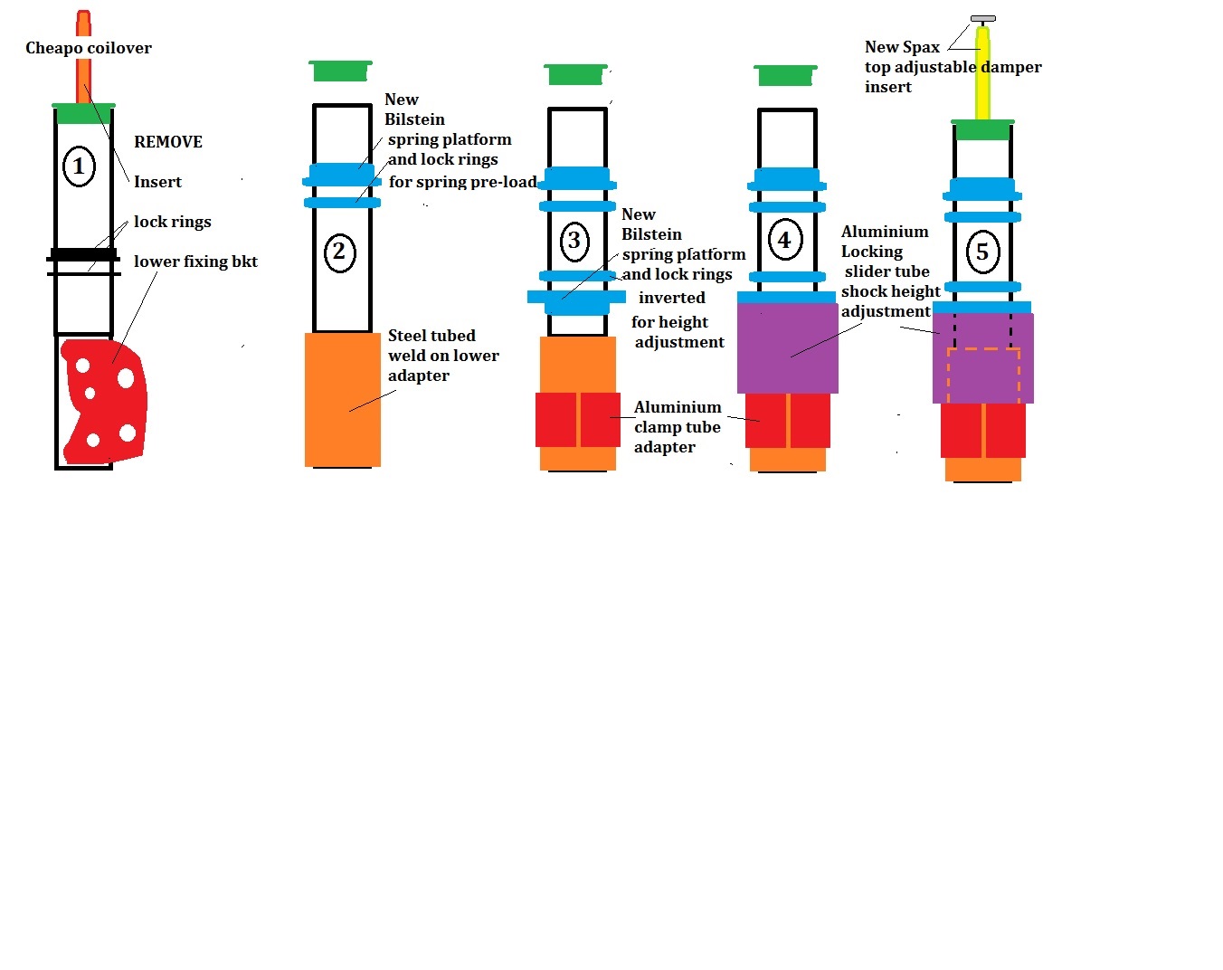
quick pic of the plan...
I wanted to use an old coilover with a thread to match the gp4 bilistien spring plates which i believe are m52..
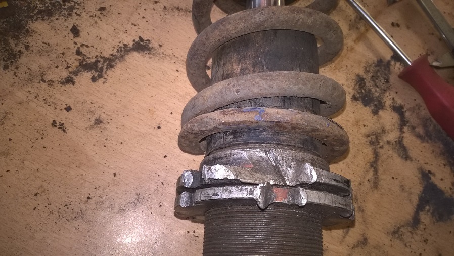
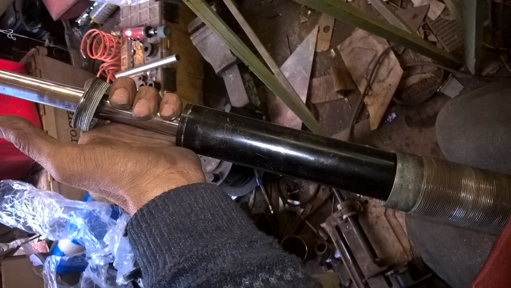
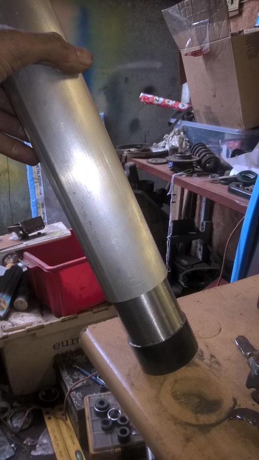
so i found a pair of "raceland" coilovers..they are total rubbish..but i dont need any of the assy only the outer tube...
so strip the "raceland" down to a bare tube..
Next checking the thread for the gp4 spring adjuster plates..
the thread was the correct size but had damage so filed the threads back into the tubes..
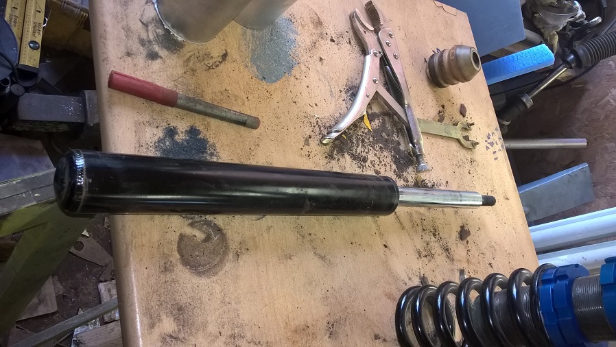
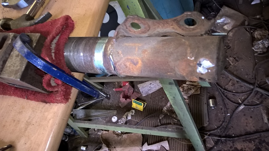
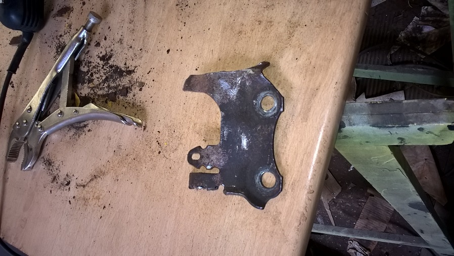
time to remove the old fixing brackets
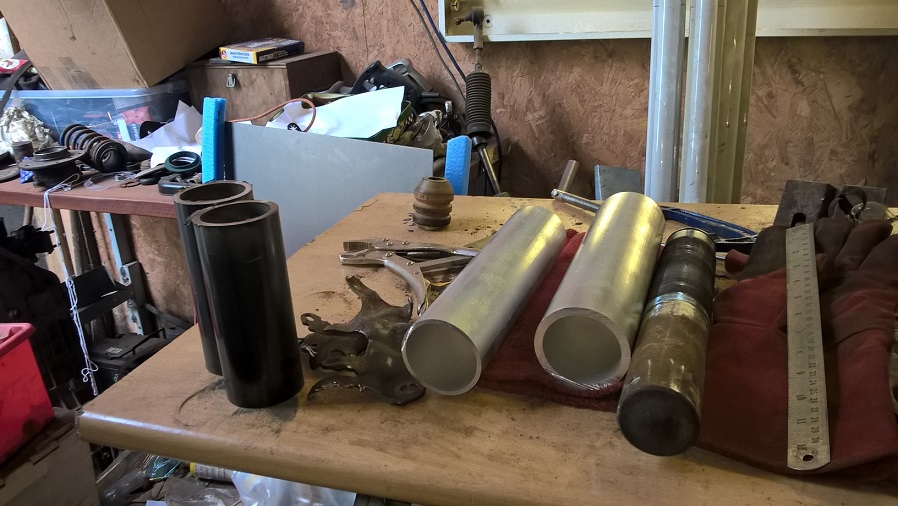
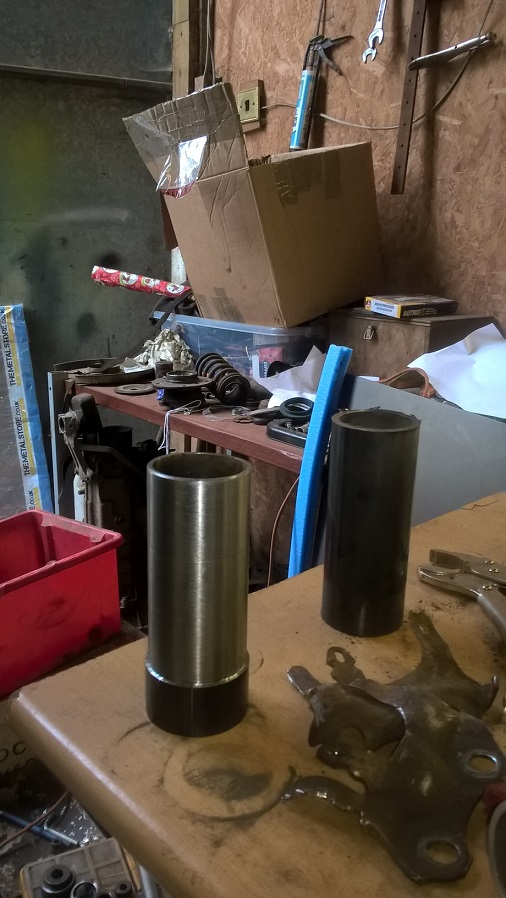
ordered a selection of tubes ..ready for the conversion..
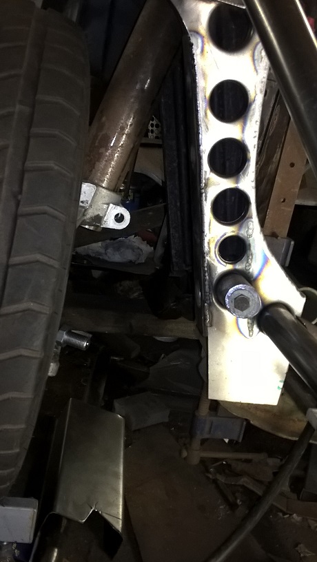
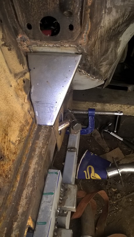
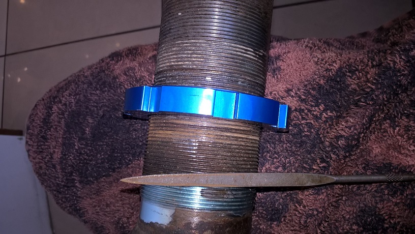
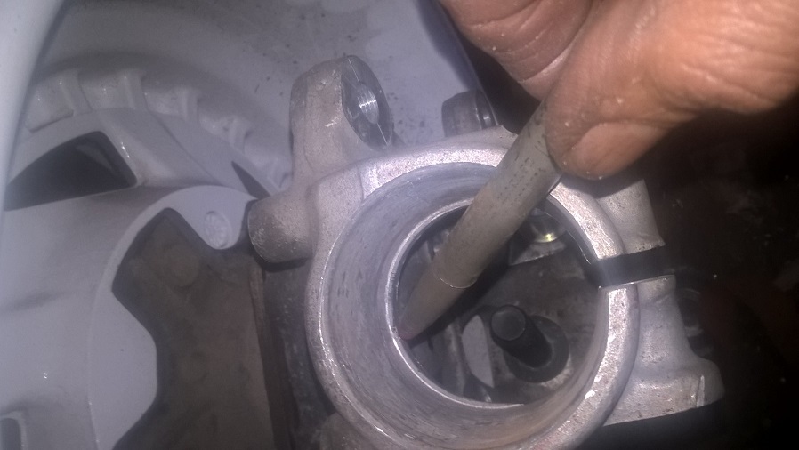
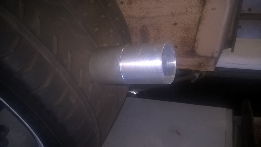
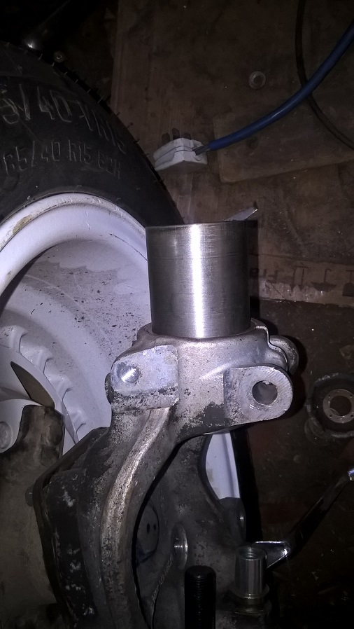
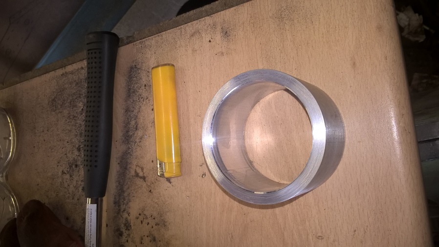
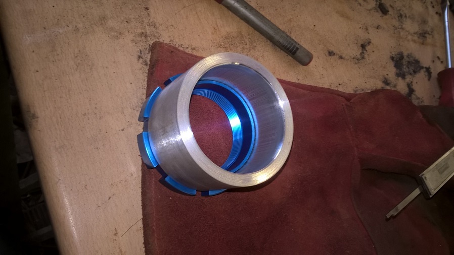
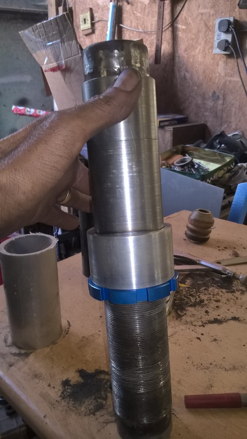
first to make is the ally clamp ring..this goes in the hub and will allow the coilover to slide up and down for height adjustment..
it sits on the lip shown here..
here fitted( before i put the slot in)
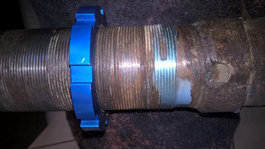
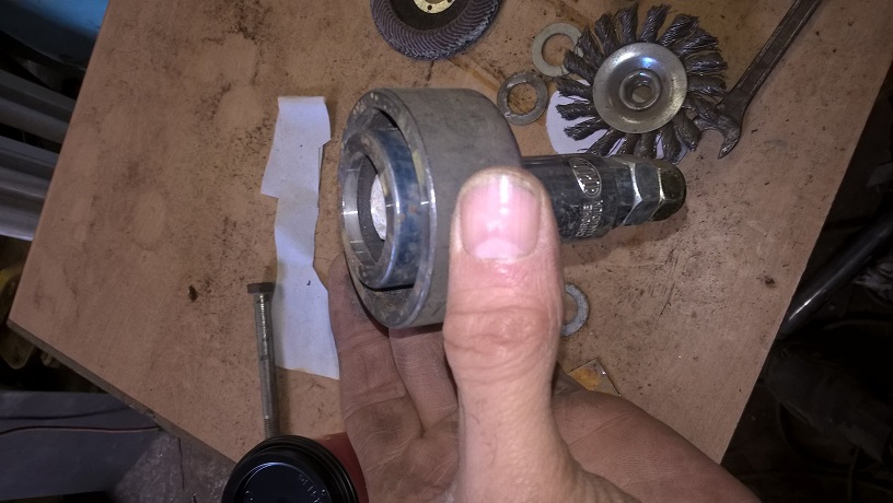
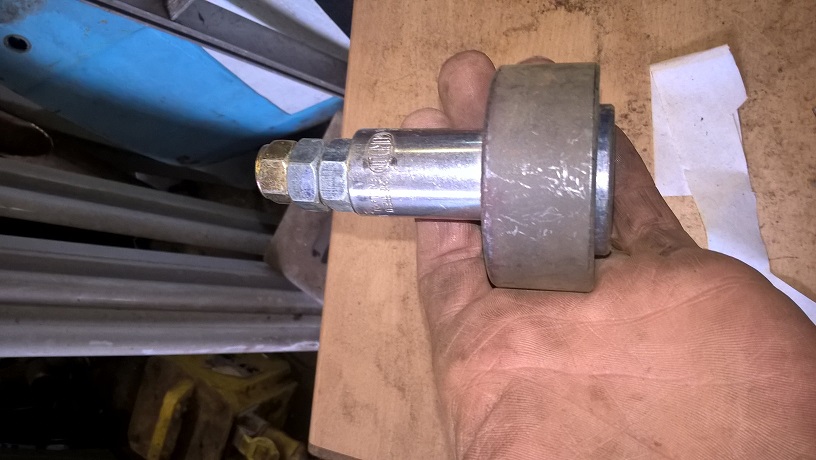
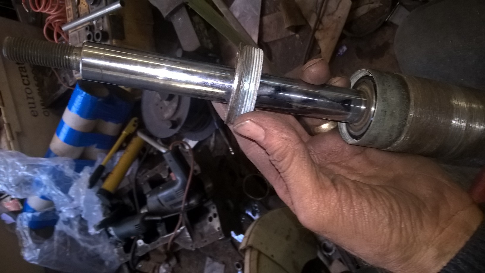
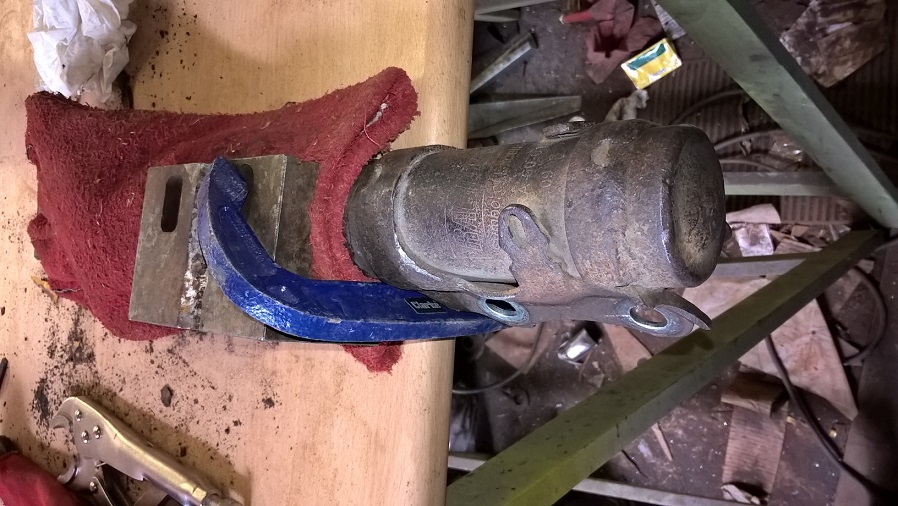
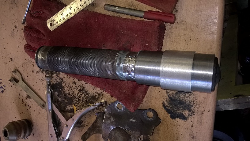
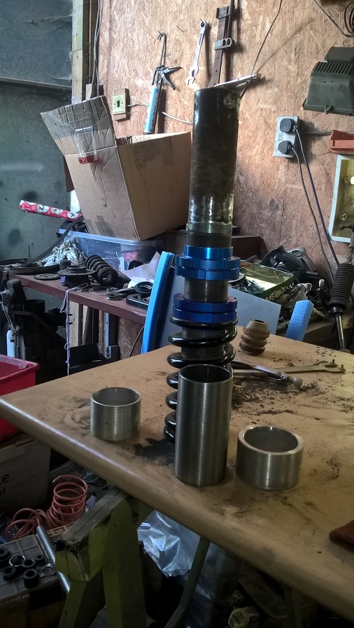
next up is the clamp body for the coilover lower section...this will be welded to the lower part and will enable the coilover to slide through the clamp ring...
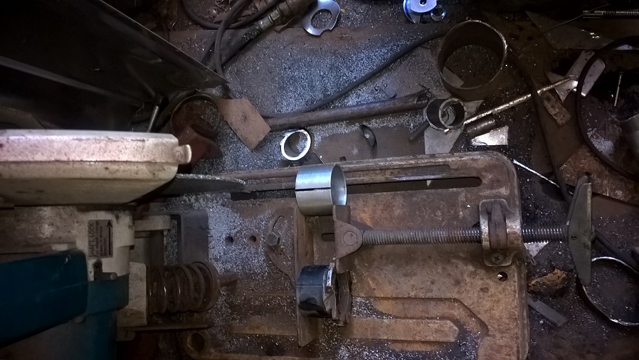
check it fits on the tube...
and the split ring on the new tube..
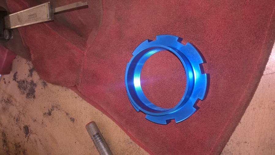
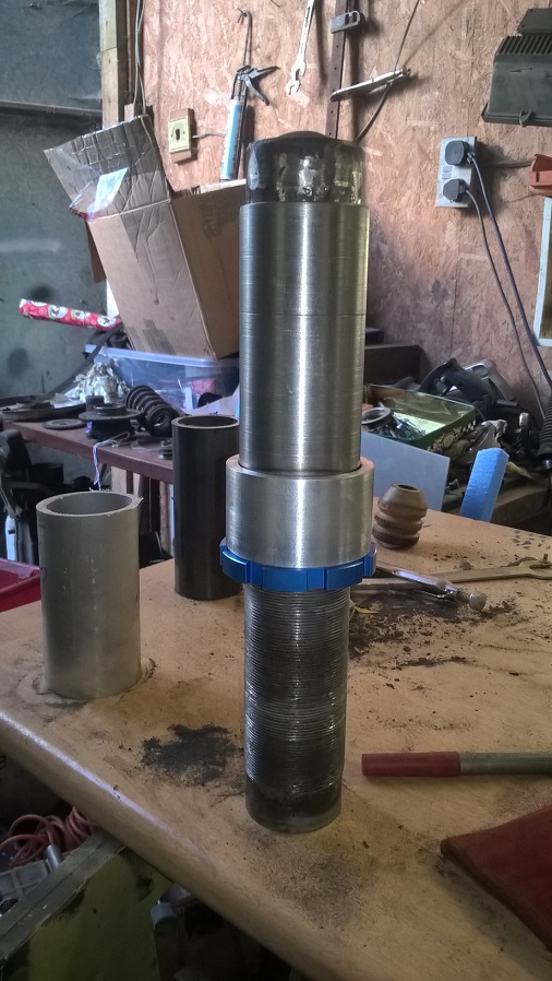
because ive modded the attachment so i can slide and clamp for height adjustment..i needed to make a locking ring to keep it in position and give it the required strength..
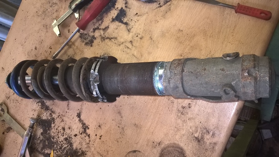
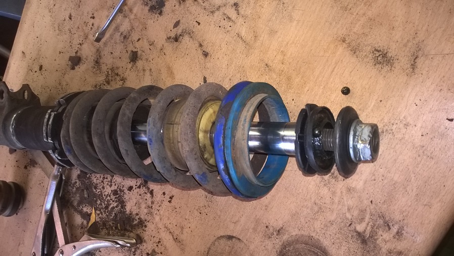
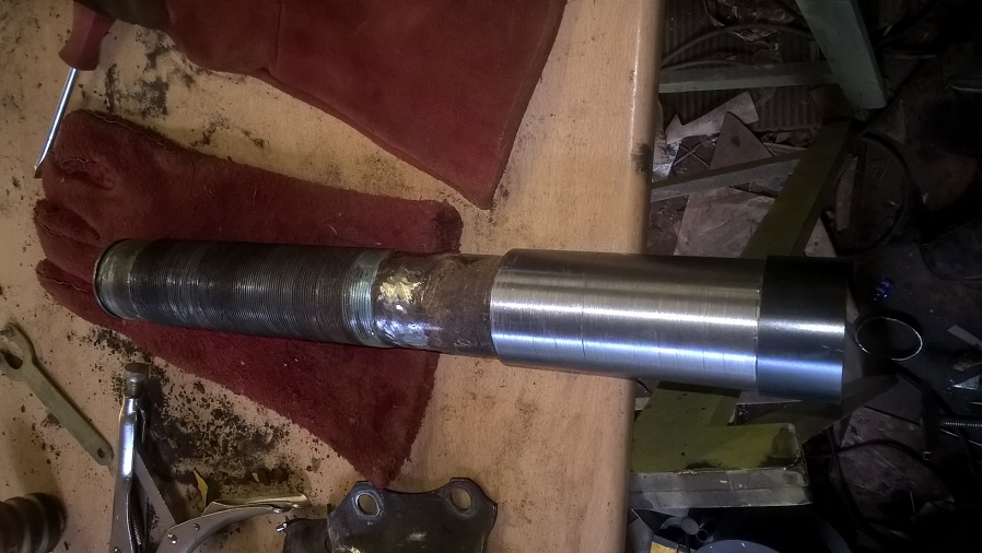
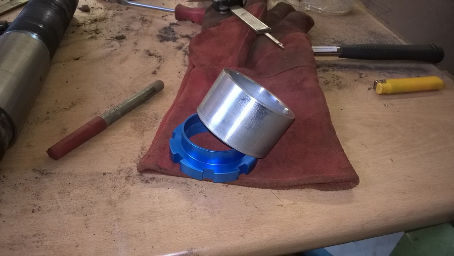
all the bits made
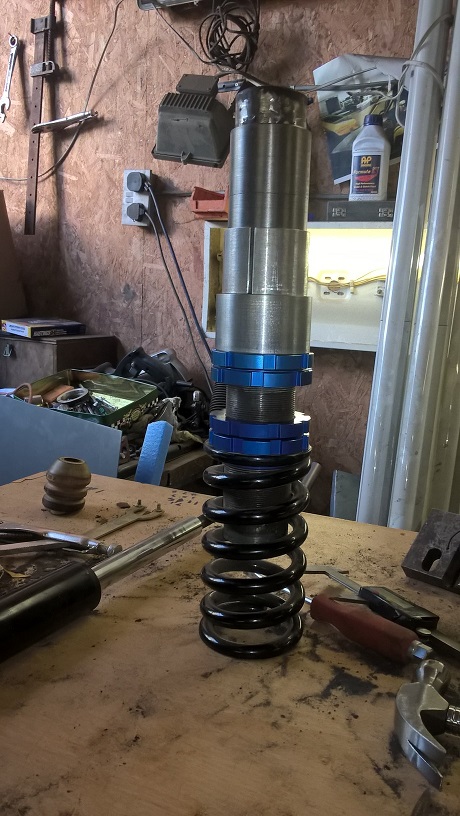
and assembled on the "raceland" body..not welded yet...
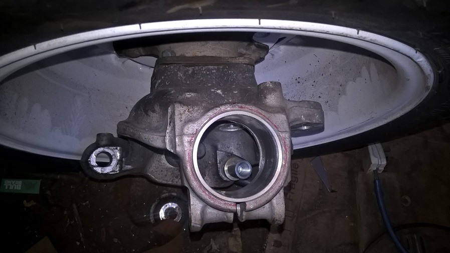
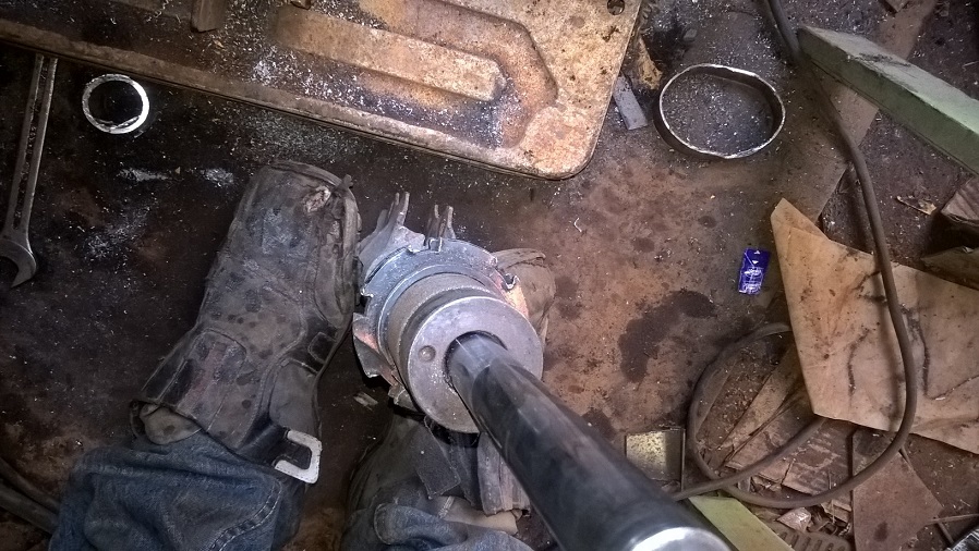
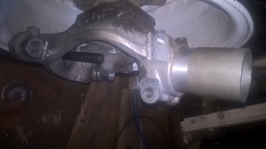
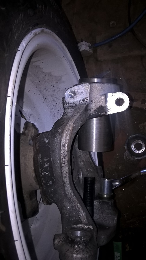
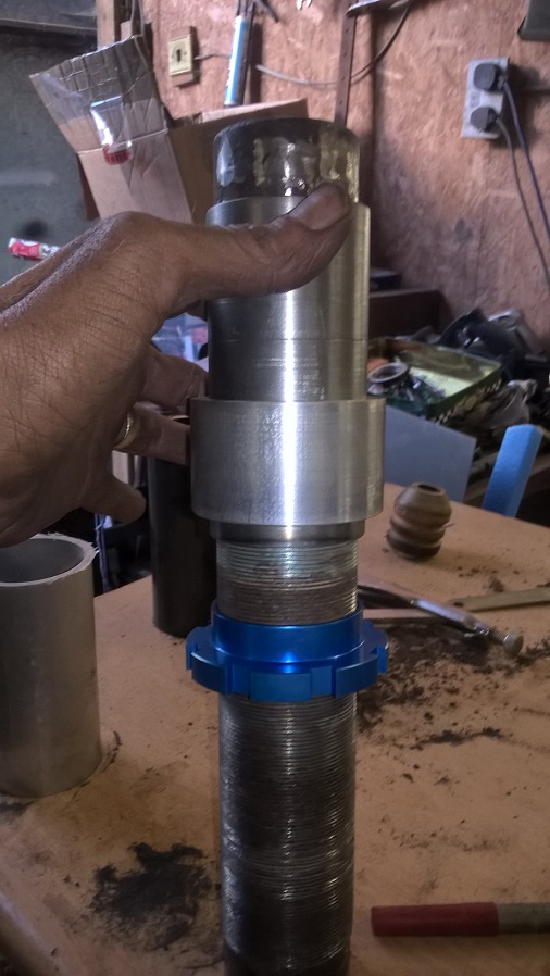
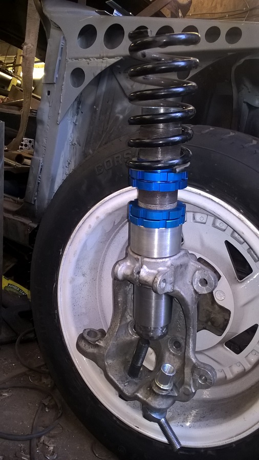
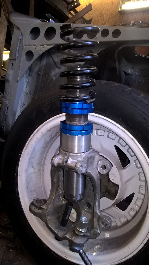
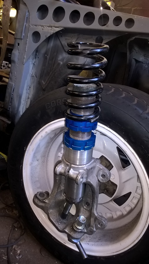
quick trial fit in the front hub..to check the finished height..
so far so good...
i am going to use Koni top adjustable damper inserts...i was going to use spax but they come complete as a whole unit so koni it is......but i cant order any yet untill i no the weight of each corner...then i can sort my springs...then i can match the dampers...so for now i will throw an old set in for mock up purpose..
cheers mark
Great work as usual
loving this
Killing it mate!
You should put these struts into production. I'd buy a set
Keep it up
Matt
.
Last edited by Matt75; 17-04-2017 at 09:03.
.
Last edited by Matt75; 17-04-2017 at 09:03.
Nice work as always,
Thanks for taking the time to photo document the entire exercise.
It's a great learning tool.
Shaun
Cheers mate...its a good reference for me..when i do the other side...cheers mark
cheers mate...nearly done 70% of one side..lol..
Thanks matt ..hows yours coming along...cheers mark
Cheers mate
Very small update...daily driver needed engine work ..so only got a couple hours on it this week...
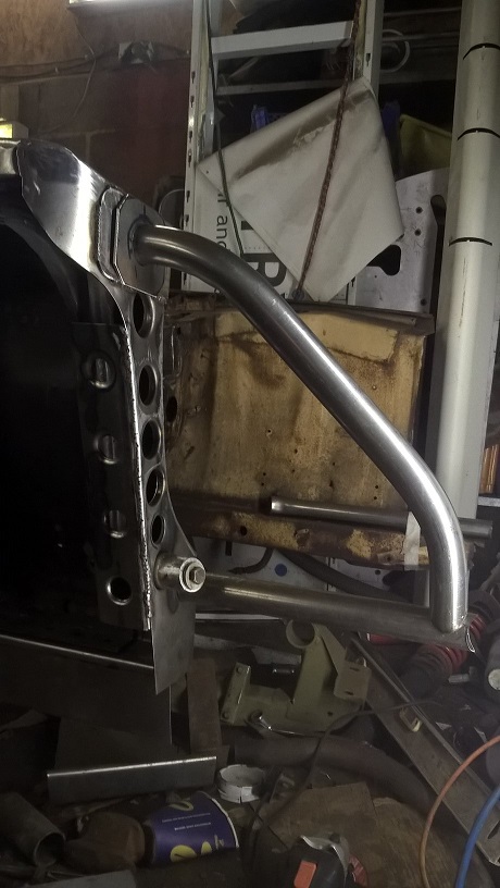
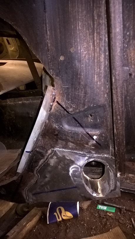
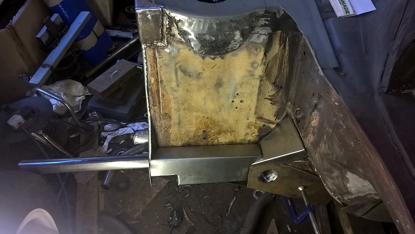
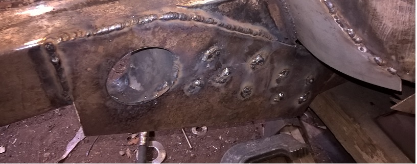
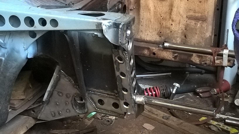
outer strength panel clamped in place ready for welding..
all welded ready for grinding..
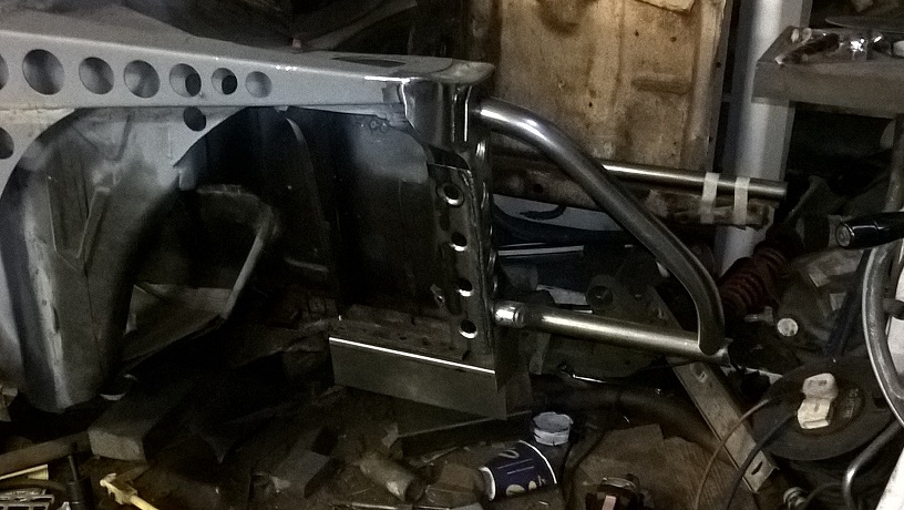
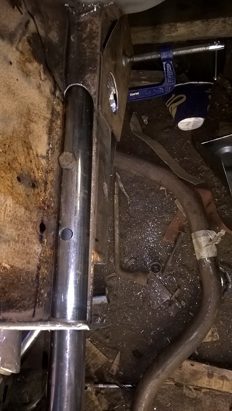
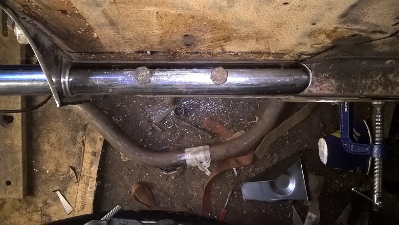
i also tubed the chassis rail...and made the inner strength plate and welded it all together..
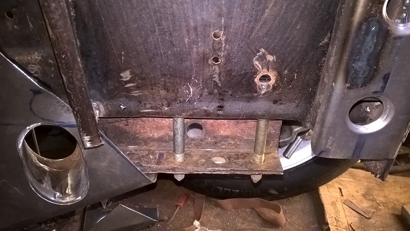
i added a 3rd bolt for the crossmember..because to remove the front tubed chassis i will have to remove the 2 outer bolts and i would like the crossmember to stay in place...
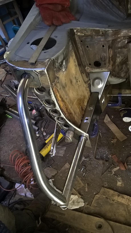
and a couple of shots of the front so far..
cheers mark
Awesome as always.
Bit slow on mine. But hopefully back into it next week
Cheers
Matt
Hi Mark (madragon199) Iv just joined this forum after finding this project a couple months ago an following with awe! Absolute mega work! I also have a soft part for anything Zakspeed and anything wide bodied like the old quattro S1 and anything group B an 80's era styling. Going to be starting my own wide body project soon as i enjoy fabrication as my hobby so what your doing just makes me droool!
Thanks mate...
Yes, same as you love all the over top styling...
Look forward to seeing yours progress...takes ages so be prepared..
cheers mark
Yeah styling that make it look like its already going 200mph.
Yeah the best way to work out projects is take you wanted time scale. "6 months" and times it by 4 and you get somewhere close to the time it will actually take "2 years"well thats how it went for the stang. Wanted it done in 6 months an spent 2 years doing it!
I was really impressed with your use of the hydraulic hole punch as swage. And the telegraph pole as a form, that i did like! What do you do as a job?
The workman ship with this is just stunningI feel like i need to go back to school just reading it!

Thanks Rob...
At the moment i own a hair salon.!!!!!(married a hair stylist)...
But i was a marconi man "tool maker"...then i ran sheet metal shop...then i was partners in a industrial machine repair buisness...and most important i am an "essex boy" so cars are in our blood...lol...
Time scale X 6 i recon....
cheers mark
Cheers dave...
I think the art is using the "wrong" tool to produce the right job....i think we all wish we had this and that...but at the end of the day we have whats availablr to us...
but its a fun challenge working out how to make something without the correct tooling...
cheers mark
I did notice the empty hair product box in the escort on one of your photos. Best thing about having a hair stylist is the family is the free hair cuts! Mother in law does mine so always got to keep her happy lol.
Ah explains why you seem to be breezing through the sheet metal work! I use to be a rally mechanic which has always given me a soft spot for a group 4 escort")
but now i sit behind a desk organising cars to go testing so getting back on the spanners on the evening has really become a joy again, too much knee pain when it was my job to do it in the evening as well..
Time doesn't really matter if you enjoy the build. Sometimes prefer to tinker with it then drive it.
double post
Last edited by Rob_G; 12-05-2017 at 14:02. Reason: double post
Yes Dead right....its the build for me to...i can spend all week planning...and then actually get work done on my one day off...
cheers mark
 Posting Permissions
 Reply With Quote


Bookmarks