-
.jpg)
Sierra cosworth turbo race car
QMN saloon car championship
RETRO Motorsport -
Re: A racing bmw 316, hopefully the worlds most powerfull Atmo M10
Fetch it here, I will set my russians on it
Comment
-
Re: A racing bmw 316, hopefully the worlds most powerfull Atmo M10
What size fuel tank are you running? Do you fuel it just for the race distance + a few laps?
As its a very solid German BMW, getting the weight down is going to be very difficult. So what do the regs say about different roof and door materials? Ie GRP?
Can the cage be cut down at all?
Can the seat be replaced with a lighter one?
Are you allowed to run with a plastic windscreen?
Can the brake disks be replaced with lighter ones?
Are you using the lightest fasteners?
Do you run a handbrake? Do you need to?
Are you running one back box or two?
As a hillclimber, I'm always thinking about removing stuff, and saving weight. It easily becomes an obsession.Comment
-
Re: A racing bmw 316, hopefully the worlds most powerfull Atmo M10
my background was sprinting so i too used to be obsessed with removing every last scrap of weight, but on a circuit car you do have to hang back slightly or teh car becomes too fragile and you stuffer dnfs through stupid fatige failures,
the car currently has an alloy 12 gallon escort tank, but i only fuel it with enough to do the race in hand.
the shell has to remaqin origonal steel, unboltable panels can be replaced with GRP etc, the bootlid for instance is a single steel skin, the doors have been hacked to bits and there is very little to them.
cant make discs lighter without making them smaller, as they are race discs on alloy bells they are lighter than the oe equipment
fasteners etc, to be honest its cost has to be borne in mind
exhaust is a twin box, i could probably of got away with one, but i want to make sure i get through plenty of noise tests first!
handbrake? whats that? theres not a single component left of the handbrake system on the car
as for the cage, i wont do anything to it otherwise it invalidates its msa certification, but if i reshell the car i will use a lighter one,
seats about as light as they go without going to carbon fibre
all the glass is plastic including front screen
this car was build as a high powered turbo so i wasnt obsesive about weight when i built it, but my previous car i had gone as far as drilling brake drums, i put the drives shafts and hubs in a lathe and lightened them, even replaced the oe door catches with garden gate latchesLast edited by Graham; 08-06-2009, 17:10.Comment
-
Re: A racing bmw 316, hopefully the worlds most powerfull Atmo M10
using a strip of masking tape on both front and rear edges of teh boot lid, i trimmed it down a bit, saving a tad over 400 grams in teh procees
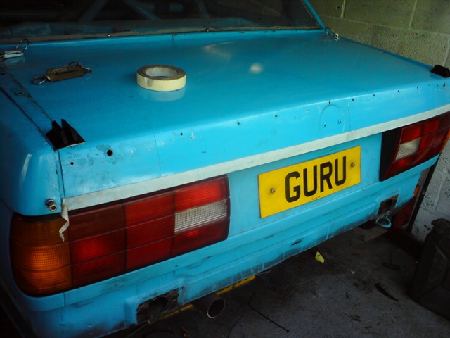
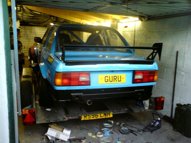
also heavy spoiler has gone, replaced by a combination of a richard grant replica capri spoiler and a cheapo "wing" off ebay, i had to device my own method of bolting teh wing together because i dont recon it would of sayed in one piece for more than a lap of teh local high st on a saxo let alone the rigours of a race, it should actually have another element, but i darnt fit it for fear of it coming off!

new spoiler combo has saved 5kgs, and if it behaves ok at speed i might take one of the spoilers off and save a bit more weight
the car looked crap without the bumper so i painted the bottom of it black to visually put it back
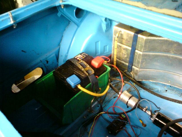
i've tried the car with a much smaller battery, it still cranks plenty fast enough so thats another 5kg saved. in total teh cars down to 907kgs which is almost 100kgs lighter than when it was in turbo form, given a grp bootlid and no spoiler it could be down to 900kgs dead, but after that its going to be hard to find any significant further savings without spending a fortune
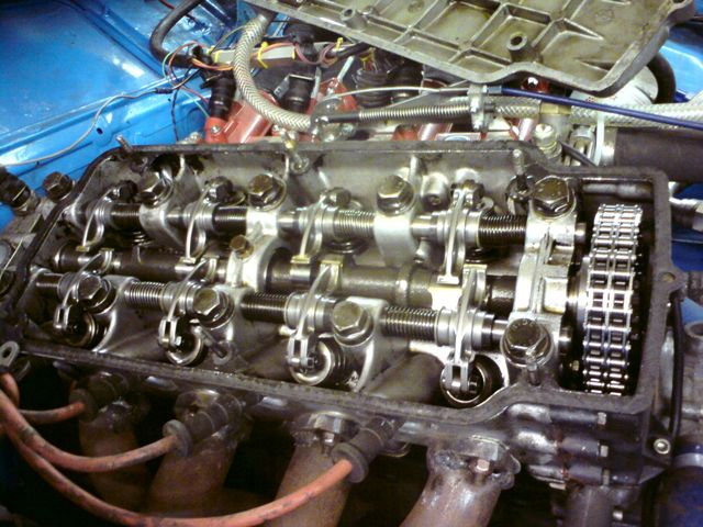
lastly a quick tappet check, i just found one exhaust a tad tight, which is good news meaning nothings wearing out!
Comment
-
Re: A racing bmw 316, hopefully the worlds most powerfull Atmo M10
ya doin good graham if ya really want ill scrape all the shit off the bottom for ya ...
hows about stuff like cutting the box that the battery sits in down? or doing away with it all together ?
lighter rear lights?
then i guess next thing is holes in everything?? Wanted: Second Hand Tremec TKO 500, 600 or T56 Gearbox... Cash Waiting
Any small welding, fabrication, engineering, paint or mechanical works undertaken, please PM for details.
It would seem my computer skills are not good enough !!
thanks Guys !

Comment
-
Re: A racing bmw 316, hopefully the worlds most powerfull Atmo M10
thanks for teh offer of scraping ant, but that stuff so stuck on its more than a scrape, you vertually have to set the car on fire to even soften it!
you can do some scraping when i have a new shell, do you want to do it alone or along with daves russians?
that box the battery is is weighs all of about 25grams, that to sort of thing you can go too far with weight saving, the other year i didnt use the box, i had another retaining method which was about 10 grams lighter, i finished a race only to find the battery had been sliding around the boot only held in place by the battery leads, i was lucky to finish!
yes holes are good but you have to cut one hell of a lot of them to save anything worthwhile plus your not allowed to cut holes in the vehicle body/structureComment
-
Re: A racing bmw 316, hopefully the worlds most powerfull Atmo M10
bugger... yeah ill do it along with daves russians if you like
yeah yeah i see what you are saying with the battery box, you are better off to carry an extra 15grams and finish than be lighter and not finish
yeah need a whole load of holes to save any real weight . is your bonnet single skin? got any sound deadening on ya roof ?Wanted: Second Hand Tremec TKO 500, 600 or T56 Gearbox... Cash Waiting
Any small welding, fabrication, engineering, paint or mechanical works undertaken, please PM for details.
It would seem my computer skills are not good enough !!
thanks Guys !
Comment
-
Re: A racing bmw 316, hopefully the worlds most powerfull Atmo M10
bonnets single skin grp, theres no sound deadening anywhere in the car, if i had the money theres an easy 50kgs to come out the car with lighter wheels carbon fibre seats and panels etc etc, but ultimately more time in the driving seat will probably gain me more speed than any further weight savingComment
-
Re: A racing bmw 316, hopefully the worlds most powerfull Atmo M10
yep defo agree with that graham
keep up the good work, but dont beat dave, he wont be happy
Wanted: Second Hand Tremec TKO 500, 600 or T56 Gearbox... Cash Waiting
Any small welding, fabrication, engineering, paint or mechanical works undertaken, please PM for details.
It would seem my computer skills are not good enough !!
thanks Guys !
Comment
-
Re: A racing bmw 316, hopefully the worlds most powerfull Atmo M10
i wont be happy if i cant beat davekeep up the good work, but dont beat dave, he wont be happy
__________________
although amazingly my engine was designed about 20 years before his pintosaurousComment
-
Re: A racing bmw 316, hopefully the worlds most powerfull Atmo M10
Looks better Graham, bet the bootlid feels a bit lighter now.
Have you considered not using the rear wings for a race or a qualifying just to see what its like, you never know.
I think Tony Ryan still has some supertourer rear wings for if ever you want something a bit more authentic, not sure how much they were though, but they are quite light
Sierra cosworth turbo race car
QMN saloon car championship
RETRO MotorsportComment
-
Re: A racing bmw 316, hopefully the worlds most powerfull Atmo M10
the plan is to see what "paddock" at lydden is like with and without, although its prob not for nothing that e30 m3 evo3 had a massive "flipper" on its rear wingHave you considered not using the rear wings for a race or a qualifying just to see what its like, you never know.Comment
-
Re: A racing bmw 316, hopefully the worlds most powerfull Atmo M10
Graham, have a go with the electric floor tile scrapers on that underseal.. or if your passing borrow my air one, not a lot beats it,Comment
-
Re: A racing bmw 316, hopefully the worlds most powerfull Atmo M10
I knew I recognised the name. I think I bought some GSXR throttle bodies off you via ebay, a few years back.
Have you made a new wiring loom from scratch, or is it a modified original. Lightweight wires could save a few more KG's.
I'll shut up now.
Comment
 Tweet
Tweet


 Gary
Gary


Comment